
Last November a customer sent us 320 cast steel housings, blast cleaned and primed, each with a dot peen serial on a flat beside the mounting flange. The foundry marked them; we measured the characters at 0.11 mm average, ranging from 0.06 to 0.15 mm across the batch. After our own blast and two coats of paint, 214 of the 320 codes could not be read by the scanner the assembly line uses. The line stopped for nine hours, two operators re-stamped all 320 housings by hand at about three and a half minutes each, and four were scrapped when a hand stamp cracked a 4 mm rib. The bill came to roughly 6,700 dollars. A proper mark at 0.30 mm on a machined pad would have cost 272 dollars for the same 320 parts.
*(Composite example; details changed.)*
That is deep marking on cast steel in one story. Depth is not cosmetic, it is a budget you spend against everything that happens to the surface afterward: blast takes metal off, paint fills grooves in, heat treatment grows a scale that crumbles shallow edges.
Here is the rule we quote, stated plainly: if a code must be read through paint on a blast cleaned surface, start at 0.20 mm.
Why Cast Surfaces Punish Shallow Marks
Four things fight a shallow mark, and they stack. The skin is not the metal: as-cast surface carries sand inclusions, near surface porosity and a burned layer, so the first tenths of a millimeter are inconsistent. Hardness moves across one part: we have measured gray iron at 180 to 250 HB in a heavy section and 260 to 300 HB where the same casting chilled against the mold, so a stylus set for the soft zone skips in the hard one. Mill scale and free graphite smear the groove into a ragged furrow, and that lip is what a scanner sees first. The surface is not flat either, so a fixed depth stylus lands at different true depths part to part.
Most of the cast iron part marking we run is spare parts and housings that get blasted and painted afterwards. Cast steel part marking follows the same arithmetic with one difference: the tougher matrix wears stylus tips faster, so 0.30 mm costs more per character on steel than it does on gray iron, and that difference belongs in the quote rather than in a discovery conversation later.
The Depth Numbers We Work To
These are typical shop ranges, not standards:
- Dot peen and vibrating stylus: 0.10 to 0.50 mm, set by material hardness and tip geometry. Our default on iron and cast steel is 0.30 mm.
- Fiber laser engraving: 0.02 to 0.15 mm, in one pass or several.
- Laser annealing: 0.005 to 0.02 mm. It is a color change in the oxide, not a groove, and it does not survive shot blasting.
- Electrochemical etching: 0.01 to 0.03 mm. Fine on clean stainless, useless on as-cast iron.
Depth is still a dimensional callout, so it inherits whatever general tolerance rules your print already carries, and how those work decides whether 0.30 mm means 0.30 or 0.35. When we specify a mark depth we pick the ISO tolerance grade that matches the process, as set out in our ISO tolerance grades guide.
We write depth into the drawing as a dimensioned value with its own tolerance, the same way we dimension any other feature to ASME Y14.5 conventions (ASME Y14.5), so the foundry and the machine shop both work to one inspectable number.
What Takes the Mark Off Afterwards
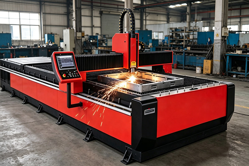
Add up what happens after marking and the minimum depth falls out of the arithmetic. Shot blast and grit blast typically remove 0.02 to 0.05 mm. One coat of liquid paint is 30 to 60 micrometers dry film, two coats run 60 to 120 micrometers. Powder coat runs 60 to 120 micrometers, and hot dip or heavy zinc can be 70 to 150 micrometers.
On a blast cleaned part with two coats, you lose about 0.04 mm to the blast and fill 0.12 mm of groove with film. A 0.10 mm mark is gone before the part ships; a 0.20 mm mark survives with margin. That is the 0.20 mm rule, and it is why we push back when a print calls out 0.10 mm and powder coat on the same page. What each film does to a recessed character is in our parts finishing guide; the coatings we run in house are on our surface treatment page.
Hardness Sets the Ceiling
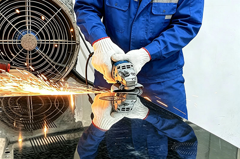
Gray iron, HT250 or Class 250, marks easily unless you hit a chilled white iron zone where the iron cooled fast against the mold. Those spots deflect a stylus and wreck tip life, and they sit exactly where someone wants a code because the surface looks smooth. Ductile iron, QT500-7 or a broadly comparable grade such as ASTM 65-45-12, marks cleanly and is the friendliest casting material we run. Cast steel, a low carbon cast grade such as ASTM A216 WCB or its 1020 and 1035 equivalent, is tougher and harder on tips, so deep marking on cast steel costs more in consumables and takes longer. Austenitic stainless castings work harden under the stylus. Above about 45 HRC, tip wear becomes a process problem, see our heat treated parts guide.
Mark after annealing or normalizing, and before a final quench and temper if the part gets blasted afterward. The alternative is a re-mark station after heat treat, a real line item and sometimes the right call. Heat treat scale has to come off first, or the character edges crumble when it breaks up.
Method Comparison for Cast Parts
| Method | Typical depth on cast iron | Survives blast? | Survives paint? | Read by scanner? | Cost per part | When we choose it |
|---|---|---|---|---|---|---|
| Dot peen or stylus | 0.10 to 0.50 mm | Yes above 0.20 mm blast cleaned, 0.30 mm on as-cast skin | Yes if deeper than film | Good on a machined pad | Low | Default for castings that will be blasted |
| Fiber laser engraving | 0.02 to 0.15 mm | Only above 0.10 mm | Marginal under two coats | Best contrast on clean iron | Medium | Machined pads, fine characters, no heavy blast |
| Laser annealing | 0.005 to 0.02 mm | No | No | Poor on dark iron | Low | Parts that never see a blast cabinet |
| Electrochemical etching | 0.01 to 0.03 mm | No | No | Fair on stainless | Low | Clean machined faces, never as-cast skin |
| Cast-in raised characters | 0.5 to 1.5 mm proud | Yes | Yes, film rounds edges | Poor without a flat around them | High tooling, nothing per part | Frozen part numbers at volume |
Cast-in characters cost tooling money up front and nothing per part afterward, so they win on unit cost and lose the moment a revision changes. The full comparison is in our part marking methods guide, and the laser settings we run are in our laser marking guide.
Sequence: Where the Marking Station Sits
| Step | Why it sits there | What goes wrong if you move it |
|---|---|---|
| Blast or grind the area | Removes scale and sand skin | Edges crumble, depth varies by 0.05 mm |
| Rough machine | Exposes the pad | Mark first and the facing pass removes the code |
| Mark | Last chance on bare flat metal | Mark later and you are cutting through paint |
| Finish machine | Cuts elsewhere, nothing at the mark | A finish pass over the pad thins the code away |
| Paint or coat | Film lands over a known depth | Marking after breaks the corrosion barrier |
| Final inspect and re-read | Catches a worn stylus before the truck leaves | Failure shows up at your customer's line |
The rule we teach programmers: mark after the last operation that removes metal anywhere near the pad, and before the last operation that covers the surface. If a finish pass still has to cross the pad, it belongs above the marking step in the sequence, not below it.
Scanner Readability Is Contrast, Not Depth
A DataMatrix read after blasting needs contrast more than depth. A shallow mark with a polished bottom on dark cast iron often reads better than a deep one with a torn bottom. Depth gets you through the blast, contrast gets you through the scanner.
Give the code a quiet zone of clear metal, and size the module to the surface instead of digging deeper. Our rule of thumb: on an as-cast face at Ra 12.5 to 25 micrometers, size the module at 0.30 to 0.50 mm, roughly ten times the peak to valley height, and go bigger rather than deeper. Roughness and what we hold are in our surface roughness guide.
Pick a machined pad when one exists, keep off parting line flash and gate areas, stay off radii, and clear the datum features machined later. A raised lip on a locating face is a burr problem, see our deburring guide.
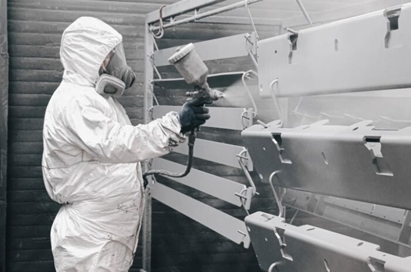
We mark on the machining center or at a dedicated station, depending on volume, and the code goes into the first article package with location, depth, character height and a read result from the line's own scanner. We re-verify after coating, because a mark that reads at the station is not automatically readable under 120 micrometers of film.
On heavy part marking, machine beds, pump bodies and counterweights in the 40 to 300 kg range, the part does not travel to the machine. We bring a portable dot peen frame to it, which makes pad location matter more than on a casting you can put in a vise, and it is one of the cases where we ask for a photograph of the surface before quoting.
What buyers actually ask us
Can you just make it deeper so it survives anything?
We could, and we usually advise against it. A 0.50 mm mark in a 4 mm cast rib is a structural decision, it raises a burr someone then has to remove, and past a point it does not help the scanner. We would rather spend the money on a pad and the right sequence.
Our foundry casts the part number in. Isn't that enough?
Until the revision changes, yes. Cast-in numbers freeze when the tooling is cut, so we cast the part number only and add revision, heat and date code with a method that can change. That reasoning is in our cast part identification marking guide.
Why not laser it at the end and be done?
On machined aluminum that is often what we do. On as-cast iron the contrast is unreliable, because mill scale and graphite make identical settings read well on one part and vanish on the next. We save laser for faces we have cut.
Who owns the traceability record?
We do, until the part leaves. Traceability marking only counts if the record survives the part: we keep the code, its location, the measured depth and the read result, tied into the record in our traceability guide, and on medical work we add what a UDI program needs, covered in our UDI marking guide.
FAQ: deep marking on cast iron and cast steel
How deep should a mark be to survive shot blasting and paint?
Start at 0.20 mm on a blast cleaned surface that will be painted, and go to 0.30 mm on as-cast skin. Blast removes 0.02 to 0.05 mm and two coats of paint fill 60 to 120 micrometers, so anything under 0.15 mm is gone before the part ships.
Does laser annealing survive shot blasting?
No. Annealing only colors the surface oxide, about 0.005 to 0.02 mm deep, while blast removes 0.02 to 0.05 mm. Use it on parts that never enter a blast cabinet, and use dot peen or deep engraving on castings that do.
Should castings be marked before or after heat treatment?
After annealing or normalizing, and before a final quench and temper if the part is blasted afterward. Remove heat treat scale first or the edges crumble. Above about 45 HRC, tips need a shorter change interval.
How do we know the code will still scan after coating?
We do not guess. We mark samples at two or three depths, run them through the real blast and coating line, read them with the scanner the assembly line uses, and photograph the result. That is part of the free DFM review, and the numbers go into the first article report. Sequence changes belong in the same review, which is what our DFM analysis covers before anything is tooled.
Let's talk about your casting
So here is what 23+ years and 200+ CNC machines have taught us: put the code on a pad, blast first, go 0.30 mm on iron and cast steel, keep it clear of what gets machined, and read it again after the coating line. If you have a casting with a code on it and you are not sure it will still be there in six months, send us the drawing, the material and the finish callout. We will tell you where the mark belongs and how deep it needs to be, as part of the free DFM that comes with a quote inside 24 hours. We hold ±0.01 mm and work to IATF 16949, ISO 9001 and ISO 13485. Tell us what the surface sees after we mark it. Reach us on WhatsApp at +86 17620300785 or by email to gongtianbao@xhlmarketing.com. Talk to our team.