
Tolerance is the acceptable range of deviation from a nominal dimension. It is the single most important factor driving the cost and difficulty of a machined part — and the one most commonly over-specified.
Standard vs Tight Tolerances
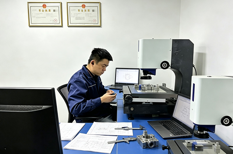
A typical CNC shop holds ±0.05 mm as standard and ±0.01 mm as precision. Tighter tolerances such as ±0.005 mm are possible on critical features but require slower cutting and more inspection.
How Tolerance Affects Cost
Every step toward tighter tolerance adds slower feed rates, specialized tooling, more set-ups and additional inspection. A ±0.01 mm part can cost several times more than a ±0.05 mm part of the same shape.
We counted those days in our CNC machining lead time benchmarks, including the stages a supplier cannot compress no matter what you pay.
Once you leave the machine and enter sheet metal, the rules change again: general tolerance classes, per-process standards and cost bands are set out in our sheet metal fabrication tolerances guide.
Avoid Over-Tolerancing
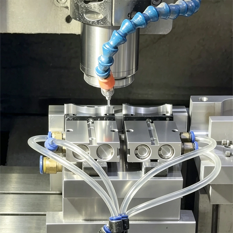
Only critical, mating features need tight tolerances. Loose tolerances elsewhere keep the part economical. Over-specifying tolerance on non-critical surfaces is the most common design mistake we see.
Geometric Tolerancing
Beyond size, GD&T controls flatness, position, concentricity, parallelism and run-out. Use it to communicate how features must relate to each other, not just their size.
Once production starts, that evidence lives in a control plan, and our control plan guide lists the four columns that make one worth auditing.
Specifying Tolerance Correctly
State a general tolerance in the title block, then flag only critical dimensions with tighter values. This keeps drawings clean and quotes accurate.
The same discipline applies to formed parts, where bend-angle error multiplies across every flange: three bends will not hold a ±0.2 mm box. Our bend tolerance accumulation guide sets out the arithmetic.
What Are CNC Machining Tolerances?
CNC machining tolerances are the permitted deviation between the nominal dimension on your drawing and the dimension measured on the finished part. Every machined part deviates; a tolerance states by how much a part may deviate and still fit and function. It is expressed either as a bilateral value such as ±0.05 mm, as a unilateral range such as +0.10 / 0.00 mm, or as a limit dimension such as 19.90 – 20.10 mm.
Three things determine whether a tolerance is cheap or expensive to hold: the process used to make the feature, the size of the feature, and how the tolerance is verified. Machining tolerances that are never checked cost nothing to specify but deliver nothing either — which is why every tight call-out should be paired with a measurement method and an inspection plan.
Location tolerances follow different rules from size tolerances: our true position guide walks through the datum frame, projected zones and what we can realistically hold.
Which method proves each of those numbers is a separate decision, and it is the one most drawings leave open: our CNC inspection methods guide compares CMM, air gauging, vision and hand tools by tolerance band.
Machining Tolerances Explained: Reading ISO 2768 on Your Drawing
Most drawings do not put a tolerance next to every dimension. Instead they carry a general-tolerance note in the title block, most commonly ISO 2768-mK. The first letter is the class for linear and angular dimensions from ISO 2768-1 (f fine, m medium, c coarse, v very coarse); the second is the class for form and location from ISO 2768-2 (H, K, L). Any dimension without its own tolerance then inherits the value below.
| Nominal size (mm) | f (fine) | m (medium) | c (coarse) | v (very coarse) |
|---|---|---|---|---|
| 0.5 – 3 | ±0.05 | ±0.1 | ±0.2 | — |
| over 3 – 6 | ±0.05 | ±0.1 | ±0.3 | ±0.5 |
| over 6 – 30 | ±0.1 | ±0.2 | ±0.5 | ±1.0 |
| over 30 – 120 | ±0.15 | ±0.3 | ±0.8 | ±1.5 |
| over 120 – 400 | ±0.2 | ±0.5 | ±1.2 | ±2.5 |
| over 400 – 1000 | ±0.3 | ±0.8 | ±2.0 | ±4.0 |
Read that table functionally: under class m, a 10 mm pin location defaults to ±0.2 mm while a 350 mm housing length defaults to ±0.5 mm. If either needs to be tighter, that single dimension earns an individual tolerance and the rest of the drawing stays at m. Two boundaries catch people out: below 0.5 mm nominal the standard does not apply at all, and class v does not cover features under 3 mm.
Form and orientation are governed separately. ISO 2768-2 class H gives 0.1 mm straightness and flatness over a 30–100 mm surface, K gives 0.2 mm and L gives 0.4 mm; circular run-out is 0.1 / 0.2 / 0.5 mm respectively at any size. Note what Part 2 does not cover — position, concentricity, cylindricity and profile stay uncontrolled unless you draw a GD&T frame for them.
CNC Machine Tolerance by Process: What Each Operation Actually Holds
A CNC machine tolerance is not one number for the whole shop. It varies by operation, by feature size and by material, and quoting the tightest number on a drawing for every dimension is the fastest way to make a simple part unaffordable.
| Process | Routinely held | Held with care | Notes |
|---|---|---|---|
| CNC turning | ±0.05 mm | ±0.01 mm | Diameters are repeatable; long slender parts need support |
| 3-axis CNC milling | ±0.05 mm | ±0.01 mm | Multiple set-ups add stack-up, not capability |
| 5-axis CNC machining | ±0.02 mm | ±0.01 mm | One set-up removes re-fixturing error |
| Precision grinding | ±0.005 mm | ±0.002 mm | The step to take when turning is not enough |
| Wire EDM | ±0.01 mm | ±0.005 mm | Slow, but independent of material hardness |
The 5-axis line deserves emphasis: five-axis work rarely holds a tolerance that three-axis cannot, but it reaches every feature in a single clamping, so the geometric relationships between features survive. That is a real advantage when position tolerances rather than size tolerances are driving the design. Whether the fixture can hold that relationship through a tilt is a separate question, covered in our 5-axis fixturing guide.
Precision CNC Machine Tolerances: Matching Tolerance to Function
Precision CNC machine tolerances should be spent only where they buy function. Ask four questions per feature: does it mate, does it seal, does it locate, does it move? If the answer is no to all four, general shop tolerance is almost certainly enough.
Where the answer is yes, tolerance rarely travels alone. A bore that locates a bearing needs a fit system — ISO 286 codes such as H7 or k6 — rather than a bare ± value, because clearance depends on both members. A face that seals needs flatness and surface finish alongside its size tolerance. A shaft that rotates needs run-out controlled, which is a form tolerance, not a size tolerance. Writing ±0.01 mm on all three does none of these jobs.
Which method belongs on the drawing is its own decision, covered in our guide to part marking methods: laser anneal, engraving, dot peen, scribing, etching and ink, compared by depth and cost.
Ruijin machines to ±0.01 mm as its quoted precision capability, with IATF 16949, ISO 9001 and ISO 13485 systems behind the measurement. Where a drawing asks for high tolerance metal fabrication beyond what machining should carry, we will say so at quotation rather than discover it at first article.
FAQ
What are CNC machining tolerances?
CNC machining tolerances are the allowed difference between the nominal dimension on a drawing and the measured dimension on the finished part. They are written bilaterally (±0.05 mm), unilaterally (+0.10 / 0.00 mm) or as limit dimensions (19.90 – 20.10 mm). Dimensions that carry no individual tolerance inherit the general tolerance noted in the title block, usually ISO 2768-mK.
The other half of the problem is proving it on paper: which characteristics get ballooned, and what the report must record. See our first article inspection guide.
What tolerance can CNC machining hold?
A competent shop holds ±0.05 mm routinely on turning and milling, ±0.01 mm as its precision capability, and ±0.005 mm on selected features with slower cutting and extra inspection. Below that, grinding (to about ±0.002 mm) or wire EDM is usually the economic route rather than pushing a machining centre harder.
How tight can CNC machining tolerances be?
In production terms, around ±0.005 mm is where conventional CNC stops and grinding starts. Tighter is physically possible — ultra-precision turning reaches sub-micron levels — but cost rises steeply and temperature control, metrology and scrap rate start to dominate the quote. For almost every commercial part, nothing above ±0.005 mm is needed.
What is standard machining tolerance?
There is no single legal standard; the common commercial default is ±0.05 mm, backed by the drawing's general-tolerance note. When the note reads ISO 2768-m, standard tolerance scales with feature size — ±0.1 mm below 3 mm, ±0.2 mm at 6–30 mm, ±0.3 mm at 30–120 mm.
Machining tolerances explained: what does ISO 2768-mK mean?
It is a combined general-tolerance note. The lowercase m is the medium class of ISO 2768-1 for linear and angular dimensions; uppercase K is the medium class of ISO 2768-2 for form and location. Together they give every untoleranced dimension a binding limit — for example ±0.3 mm on a 50 mm length and 0.2 mm flatness over an 80 mm surface — without cluttering the drawing.
Why do tight tolerances cost more?
Because each step tighter buys slower feeds, sharper and more expensive tooling, additional set-ups, temperature-controlled measurement and higher scrap risk. The cost curve is not linear: a ±0.01 mm part can cost several times a ±0.05 mm part of identical geometry, because the process has to be proven on every part rather than sampled.
Do I need GD&T on every drawing?
No. General tolerances cover most features adequately. Add GD&T where function depends on relationships instead of size — the position of a hole pattern, the concentricity of a shaft, the profile of a sealing surface — and leave everything else to the title-block note. Over-using GD&T has the same effect as over-tolerancing: it raises cost without improving the part.
Need a tight-tolerance part? Send your drawing for a free DFM review and a quote within 24 hours.