
A customer in Birmingham sent us a 400 × 300 mm aluminum plate that had already been machined somewhere else, twice. Both times it measured in tolerance on the machine and out of tolerance on the bench. The flatness callout was 0.1 mm over the full face, the CMM report from the previous supplier showed 0.04 mm, and by the time the part reached the customer's inspector it was 0.12 mm. Nothing was wrong with the machine program. The part was clamped in a way that let it spring.
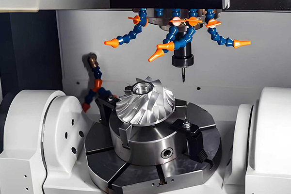
That is what 5-axis fixturing is really about, and it is the part of 5-axis CNC machining that capability sheets never mention. On a 3-axis job you clamp a part against a downward force and the table takes the load. On a 5-axis job the part tilts, gravity stops being your friend, and every clamping decision has to survive being rotated through 120 degrees.
Why 5-Axis Fixturing Is Not 3-Axis Clamping
Three things change at once when you add a trunnion.
The load direction rotates. A cut that pushes the part straight down into the table at 0° pushes it sideways at 90°. Whatever is holding the part has to win in every orientation, not just the one you clamped it in.
The clamp has to stay out of the way. On a 3-axis job you can put a big strap clamp across the top of the part because the spindle only ever comes straight down. On a 5-axis job the spindle arrives from an angle, and a clamp that was harmless at 0° is a collision at 75°. Every clamp is now a reachability problem as well as a holding problem.
The fixture eats travel before the part does. A base plate plus clamps plus the part has to fit inside the same 750 × 650 × 500 mm of travel, and the largest part we run is Ø500 × 400 mm. Budget 40 to 80 mm of stack height on a large job, and check it before you design the fixture rather than after.
The Failure Modes We Actually See
Not a theoretical list. These are the four that produce the scrap and the awkward phone calls.
Spring. The classic. Clamp a plate at four points, machine the middle, release, and the middle comes back up. It happens because the clamp was holding a bowed blank flat and the machining removed the material that was carrying the bow. The fix is to support under the cut rather than near it, and on big plates to rough, release, and re-clamp before finishing.
Lift. A heavy roughing pass puts real force into the part. In aluminum a Ø20 cutter taking a full working engagement can push with the better part of 1,000 N, and at 90° of tilt the weight of the part is no longer helping you hold it down. Our rule is that the clamping arrangement should resist at least three times the peak cutting force, because a clamp that is just barely enough will walk.
Tilt load. A 22 kg blank whose center of mass sits out from the trunnion axis generates an overturning moment that grows with the tilt angle. It is rarely the thing that breaks the setup, and it is often the thing that makes a 0.02 mm repeatability claim turn into 0.05 mm. We mount heavy parts with the mass as close to the rotary axis as the geometry allows.
Collision. The expensive one. On a 5-axis cell the spindle, the holder and the shank all have to miss the clamps, and the clamps have to miss the trunnion. We model the fixture in the machine simulation, not just the part.
How We Build the Setup
Four rules, applied in this order.
- Locate from the datums on the drawing. Not from a convenient edge. If the drawing establishes datum A as a face and datums B and C as two bores, the fixture has to reference those, because that is what the inspection will reference. A fixture that locates from the wrong surfaces produces parts that machine beautifully and fail inspection. The same logic drives how we set up large part 5-axis work, where the envelope is tighter and the fixture competes with the part for travel.
- Support under every heavy cut. Support directly beneath the material being removed, not 80 mm away from it. On thin floors this is the difference between a part that chatters and one that does not.
- Clamp low, and as few times as possible. Low-profile clamps keep the spindle's approach clear, and every extra clamp is another thing to crash into. On the 400 × 300 mm plate from the opening we ended up with three low-profile clamps and a fourth support point, and we lost a little accessibility to get it. That trade is almost always worth making.
- Prove it in simulation, then prove it in metal. Machine simulation with the real holder, the real clamps and the real kinematics. Then a first article measured on the CMM in a temperature-controlled room, because a large aluminum part measured warm is not a measurement.
Choosing the Holding Method
| Method | Best for | Watch out for |
|---|---|---|
| Modular tombstone | Small to medium parts with features on several faces | Height eats Z travel quickly |
| Base plate with low-profile clamps | Large plates and multi-face prismatic parts | Reach past the clamp at high tilt |
| Vacuum fixture | Large flat plates, non-ferrous, no through-cuts | A through-cut breaks the seal mid-program |
| Low-melt alloy support | Thin, awkward or already-complicated parts | Cleanup time on every part |
| Custom soft jaws or dedicated fixture | Repeat orders and production runs | One-off cost, needs volume to pay back |
For a one-off prototype we will usually go with a base plate and low-profile clamps, because the engineering time is short and the risk is visible. For a repeat order we design a dedicated fixture, absorb the cost as a one-off line, and the second batch is cheaper per piece.
If you already have a fixture that works, send it. We are happy to run on your tooling when the geometry allows, and our DFM analysis covers what we check before we say yes.
What Comes Back With the Quote
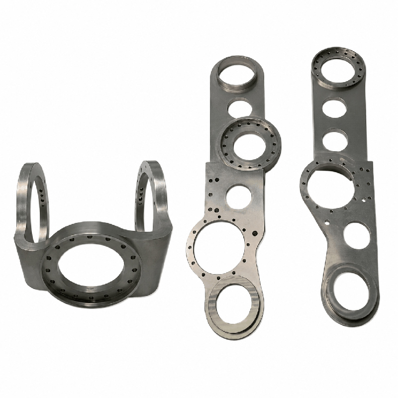
A setup sheet: where the part is located, where it is supported, where it is clamped, which faces get cut in which order, and where we expect the tolerance risk to be. It is not a formality. When a large part is going to move, the setup sheet is where we say so, and it is where you get to disagree with us before metal is cut rather than after. Set-up count also drives the price, which our 5-axis machining cost guide breaks out line by line.
Tolerances are quoted at ±0.01 mm as standard and ±0.005 mm on features you call out as critical, and both of those depend on the part being held the way the setup sheet describes. If your part geometry makes that hard, we would rather tell you in the DFM note than discover it on the CMM. Our CNC machining tolerance guide explains where those numbers come from, and our first article inspection guide shows what we hand over with the first parts, and our CNC inspection methods guide covers how those measurements are taken. Capability details for the machines themselves are on our 5-axis CNC machining service page.
FAQ: what buyers ask us
Do I need to supply a fixture?
No. We design and build it and quote it as a one-off line. For large 5-axis parts we would generally rather use our own, because we know how it behaves under tilt and we have already simulated it. If you have one that works, send it and we will assess it.
Why did my last supplier's part measure fine and then fail at my end?
Usually spring: the fixture held a stressed blank flat, the machining released the stress, and the part relaxed after it was unclamped. It is more common on large hog-outs from plate. Roughing, releasing and re-clamping before the finish pass normally fixes it.
Can you hold a part with a through-cavity on vacuum?
Only if the cavity does not break the seal. Once a cutter breaks through, vacuum is gone mid-program. For through-features we use mechanical clamping and support, and vacuum only where the part stays closed.
How much travel does the fixture use up?
On a large part, budget 40 to 80 mm of stack for base plate and clamps, inside the Ø500 × 400 mm envelope and the 750 × 650 × 500 mm of travel. It is one of the first things we check, because it is cheaper to change the fixture design than to discover the part does not fit.
Send Us the Part and Let Us Look at It
Send the model and the drawing with the datums marked. You get a free DFM note and a quotation within 24 hours, and the note will say how we intend to hold the part, not just what it will cost.
If your part has been machined twice and measured out of tolerance twice, the problem is probably the setup rather than the machine. We will tell you which, in plain language, before you commit to anything.