
Last spring a fluid handling customer sent us 480 gray iron pump housings to machine. Their foundry had stamped a four digit heat code on a raised boss beside the volute. Operation 20 faced that boss flat as part of the mounting flange, and on 78 of the 480 parts the stamp disappeared. Incoming inspection rejected the lot within a week; without the code nobody could tie the parts to a heat. The mark sat 30 mm too close to a face we were about to cut. Fixing cast part identification marking on that drawing took an afternoon.
Put the identification code on a surface no cutter will touch, at least 5 mm from edges, in recessed characters 0.25 to 0.40 mm deep on iron and steel. Cast in the part number only. Add revision, heat code and date code with dot peen or laser after machining, so a revision change does not scrap the tooling.
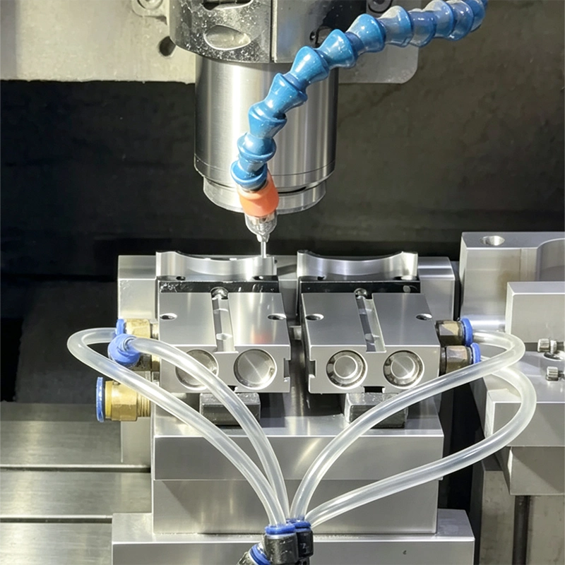
Why Cast Part Identification Marking Is Harder Than Machined Part Marking
Three things fight you at once. The surface is rough: as-cast sand texture sits around Ra 12.5 to 25 µm, so a code that reads cleanly on a machined pad turns dotted. The hardness moves: one gray iron housing measures 240 HB at a thin rib and 170 HB in the heavier section beside it, and a stylus set for the soft spot skips on the hard one. The geometry is not where the model says it is: draft, parting line shift and core shift put a pad dimensioned at 4 mm anywhere between 3 and 6 mm, so a fixed depth can leave you marking air.
Machining comes next. On our CNC milling centers we hold 0.5 mm minimum walls in aluminum and 1.0 mm in steel, so a 0.40 mm deep mark in a 1.5 mm cast rib is a structural decision, not a marking one. Methods are compared in our part marking methods guide; the reasoning behind our ±0.01 mm standard, tightened to ±0.005 mm on critical features, sits in our tolerance guide.
Where the Mark Goes on a Casting, and Where It Never Should
Rules we check, in order:
- Put it on a surface that never gets machined, or where the last pass leaves 0.3 mm above the deepest character.
- Keep it off sealing faces, gasket lands, bearing bores, threads and press fit diameters; a burr at the edge of a stamp on a gasket face leaks.
- Stay off the parting line, the gate vestige and anywhere a grinder hand is likely to go.
- Leave at least 5 mm clear of an edge, a radius or a corner, so the stylus or laser head does not ride off the end.
- Keep it on a flat face square to the tool, and prefer recessed characters: raised ones wear, chip and collect dust. Set depth against coating thickness; paint collects in the groove.
Durability is separate from machining. Housings and brackets in the automotive programs we support fall under marking non-removable parts, so the code must survive fifteen years of service, not fifteen seconds on the bench; see our automotive page.
Marking Cast Iron, Cast Steel and Cast Aluminum
| Material | As-cast reality | Methods that hold up | Methods that fail | Depth and size |
|---|---|---|---|---|
| Gray and ductile cast iron | Sand skin, free graphite, 170 to 250 HB | Cast-in recessed characters, dot peen 0.25 to 0.40 mm | Shallow laser reads gray on gray, inkjet wipes off | 0.30 mm, 3 mm characters; our baseline for industrial cast iron part marking |
| Cast steel | Tough, work hardens, mill scale, weld repairs | Dot peen, deep CNC engraving, cast-in characters | Vibrating stylus on thin ribs, shallow laser over scale | 0.25 to 0.40 mm; cast steel part marking keeps clear of weld repairs |
| Cast aluminum (A356, ADC12) | Softer, gummy, porosity under skin | Laser engraving, CNC engraving, dot peen | Hand stamping into thin walls, stamps that crack ribs | 0.30 to 0.50 mm before anodizing, 0.15 to 0.25 mm after coating |
Sequencing: Mark Before or After Machining and Coating
We machine cast blanks; we are not a foundry and do not pour castings, so every decision below starts when a blank reaches our dock.

| Sequence | What happens | Best for | Risk to watch |
|---|---|---|---|
| Foundry marks the blank, we machine after | Mark often sits on a pad that gets faced off | High volume, frozen revision, cast-in characters | 10 to 20 percent loss on machined surfaces |
| Machine first, then mark | Mark lands on a known flat at a known depth | Most of our work, best readability | One extra operation; must enter the control plan |
| Machine, coat, then laser through coating | Film stays intact around the mark | Powder coat and anodize lines | A 60 to 120 micron film swallows a shallow mark |
| Mark, then mask and coat around it | Sharpest contrast | Small batches, medical and audio faceplates | Masking labor; a misplaced mask is scrap |
Whichever you pick, the mark belongs on the control plan and the first article inspection report; our finishing guide covers what each film does to a recessed mark.
What Actually Goes in the Cast Mark
Keep the content short; every extra character costs legibility. A typical cast mark carries the drawing number and revision, the cavity number on multi-cavity tools, a heat or lot code, and a four digit date code in YYWW form.
Most buyers asking about marking on metal parts want two answers: will it read in five years, and will it survive the coating line. Both come down to size and depth. Below about 2.5 mm of character height, scanner reads start to fail on as-cast iron. On machined aluminum we hold that same 2.5 mm and read rates above 99 percent, which is also the practical floor for hand held scanning, but that is a machined surface, not metal part marking on a raw casting. We tie code content to the wider record in our traceability guide.
Write the callout per ASME Y14.5 (ASME's page); European prints cite ISO 8015 and ISO 129 instead.
Case: 78 of 480 Housings Rejected for a Missing Heat Code
*(Composite example; details changed.)*
The housing was gray iron, 340 × 280 × 210 mm. Our customer owned the tooling and foundry; we machined the blanks in eight operations, facing the flange and boring the seal bore to H7.
Rejects ran 78 of 480, or 16.3 percent, every one missing the heat code after OP20; with no traceability to a melt, the lot sat on hold for three days.
At 41 dollars of casting plus machining per housing, 78 scrapped parts came to 3,198 dollars, before three days of downtime and expedited freight. One location error cost more than 3,500 times what the marking station adds per part.
The fix: move the mark to a non-machined rib on the suction side, 40 mm clear of any machined face; switch from a cast-in raised code to dot peen after OP30 at 0.35 mm with 3 mm characters; put the mark on the control plan and first article report so it gets checked, not assumed.
That station added 18 seconds per part and about 0.90 dollars, inside the 8 to 20 second and $0.70 to $1.20 windows we quote for dot peen. Next 900 housings: two rejects, both from a worn stylus. The part runs inside our five-axis envelope: 750 × 650 × 500 mm travels, A ±120 degrees, C 360 degrees, max Ø500 × 400 mm.
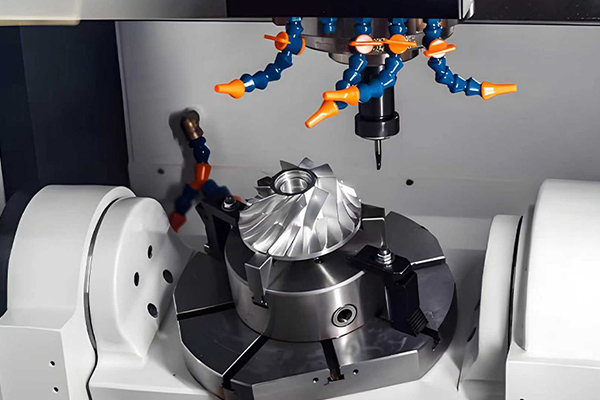
Cast Iron Component Marking: Grey Iron, Ductile Iron and What Survives
Cast part marking on iron is decided less by the alloy than by the surface you are marking. A casting gives you two very different surfaces: the as-cast skin, which carries sand texture, mill scale and graphite right at the surface, and the machined faces cut later. The process follows that choice, not the material certificate.
- As-cast skin. Dot peen wins here. A stylus displaces metal to 0.1–1 mm and reads by shadow depth, so sand texture does not change the result the way it changes a laser's colour contrast. It also survives paint, powder coat and shot blasting.
- Machined face. A fiber laser gives higher contrast, a smaller Data Matrix cell and a faster cycle, and grades well under ISO/IEC 29158 with on-axis lighting. It reads best on the flat, even surface a cutter just left.
- Grey versus ductile. Grey iron's graphite flakes and coarse as-cast skin scatter a laser beam, so identical settings land clearly on one part and faintly on the next. Ductile iron is more uniform and marks better, but the machined-versus-as-cast split still matters more than the grade.
- Hardness ceiling. Dot peen runs out around 60 HRC. Above that the stylus cannot dent the material and laser is the only route.
For cast iron spare parts marking the requirement is different from production marking: the code has to still be readable years later, after the part has been repainted in the field. That pushes the depth up and pushes the location onto a flat, non-wear face away from gasket lands and bearing seats. In industrial cast iron marking - engine blocks, pump housings, valve bodies, machine beds - the content is usually part number, heat or lot code, and a serial or date code, with the foundry's pattern and mould number added when a defect has to be traced back to a specific cavity.
What Buyers Actually Ask Us
Buyers usually open with the same suggestion: skip all this, laser it at the end. On machined aluminum we often do exactly that. On cast iron it is weaker: mill scale, sand inclusions and free graphite make identical settings read well on one part and vanish on the next. We reserve laser for faces we have already cut; the settings are in our laser marking guide.
The second pushback: the foundry casts the part number in, so the job is done. It is done until revision C. Cast-in numbers freeze when the tooling is cut, and every later revision makes the casting wrong in a way no cutter can fix. Cast in the part number only; put revision, heat and date on with a method that can change.
Then there is coating. Whether a mark survives powder coat depends on film build against depth, so we mark three depths on samples and photograph them after the coating line. That is what our free DFM review is for.
Frequently asked questions
How deep should a cast part identification marking be?
On cast iron and cast steel we specify 0.25 to 0.40 mm. Cast aluminum takes 0.30 to 0.50 mm if anodized afterward, less if marked after coating. Depth means something only against whatever covers it, so we set the number from the coating thickness.
Should a casting be marked before or after machining?
After, in most of our work. A finished surface gives a known flat at a known depth, where a scanner reads the code and inspection verifies location. Marking the blank only wins when the surface never meets a cutter and the revision is frozen.
Can cast iron be laser marked?
It can, but contrast is unreliable on an as-cast surface: mill scale and graphite make identical settings produce a legible mark on one part and a faint one on the next. On machined faces laser works well; on raw iron we prefer dot peen.
Does the mark need to appear on the first article report?
Yes, and not as a presence tick. Record location, depth, character height and a read result from the scanner the line uses. Under IATF 16949 and ISO 9001 that record makes the traceability claim defensible, and ISO 13485 programs usually add a UDI or serial on top.
What is the best cast iron part marking solution?
It follows the surface rather than the alloy. On as-cast skin use dot peen at 0.25 to 0.40 mm depth: it survives paint and shot blasting, and its contrast comes from dent depth rather than surface colour, so sand texture does not matter. On a machined face a fiber laser gives higher contrast and a smaller Data Matrix code. Above roughly 60 HRC the stylus cannot dent the material, which leaves laser as the only option.
Can you laser mark grey cast iron?
On a machined face, yes, with good contrast. On as-cast grey iron the result is unreliable: graphite flakes, mill scale and sand texture make identical settings read clearly on one part and faintly on the next. Where a code has to be scanned on the line, we either mark grey iron by dot peen or specify a machined pad for the laser to work on.
How do you mark cast iron spare parts so the code survives repainting?
Go deep enough that paint cannot fill the mark. We spec 0.25 to 0.40 mm on cast iron and cast steel, and put the code on a flat, non-wear face away from gasket lands and bearing seats. A laser mark that grades well on the bench can disappear under a thick industrial coating, while dot peen dents stay readable through it.
What does industrial cast iron marking usually need to carry?
Part number, casting heat or lot code, and a serial or date code. Foundry marks often add the pattern number and the mould number, which is what lets a defect be traced back to one specific cavity. On safety or pressure-containing parts the heat code is the one that matters most, because it is the link back to the material test report.
Conclusion
Twenty-three years and 200+ CNC machines, and castings still fail incoming inspection because the drawing put the code where a cutter was scheduled to go. Send us the drawing, the material and the finish callout; we will tell you where the mark belongs and how deep it needs to be, as part of the free DFM review that comes with a 24-hour quotation. We work to IATF 16949, ISO 9001 and ISO 13485, and we machine cast blanks rather than pour them. Talk to our team.