
The drawing arrived with a single line in the title block: TOLERANCE ±0.005 mm UNLESS NOTED. Eighty four dimensions carried that note, on an extruded aluminum amplifier chassis that measures 186 mm across. We ran it past programming first, because the answer was obvious and unwelcome: ±0.005 mm on a feature in the 180 mm size range is below IT4, and nothing on our floor produces IT4 by milling. It is a lapping operation, with temperature controlled to a couple of degrees and a part that cannot be touched by hand before it is measured. We priced it honestly, everybody winced, and then we asked the only question that mattered, which was which six dimensions actually touch another part. *(Composite example; details changed.)*
Those six were bearing bores and the faceplate register. Written as ISO tolerance grades instead of a blanket note, they became Ø25 H7 and Ø12 H7, which is IT7, and IT7 at those sizes is 21 and 18 micrometers of total band. Everything else stayed on the general tolerance block. The requote came in 38 percent below the first number, most of that gap coming out of inspection time and scrap risk rather than out of cutting time, and the first 500 pieces were delivered with 0.6 percent scrap instead of the 14 percent we had forecast for the original drawing. Same part, same machines, same shop. The only thing that changed was how the requirement was written.
This article is the arithmetic behind that conversation. We machine in Dongguan, more than 200 CNC machines on the floor, 23 years of doing it, IATF 16949 and ISO 9001 and ISO 13485 in the quality system, quotations returned inside 24 hours with free DFM attached. None of that helps if the grade on the drawing is wrong, because a wrong grade is either unpayable or unbuildable, and you find out late which one it was.
What an ISO Tolerance Grade Is, in One Sentence
An ISO tolerance grade, written IT followed by a number, is a standardized size of tolerance band for a given nominal dimension, defined in ISO 286-1 and tabulated in ISO 286-2. The number runs from IT01 at the tight end to IT18 at the loosest. The higher the number, the wider the band. The grade says nothing about where the band sits relative to nominal, which is the job of the letter in a fit callout, and nothing about form or location, which is the job of GD and T.
That separation is why the grade is useful. Once you know that IT7 at 30 mm is 21 micrometers, every shop, every gauge catalogue and every standard table in the world agree with you about what that means. A note like "machine to fit please" leaves the number up to whoever is holding the micrometer that day.
Where the Numbers Come From: Worked Out at 30 mm
The grades are not arbitrary. ISO 286-1 builds them from a single quantity called the standard tolerance unit, written i, in micrometers:
i = 0.45 × D^(1/3) + 0.001 × D, where D is the geometric mean of the size step, in millimeters.
Take a shaft you have called out as Ø30. In the standard, 30 mm falls into the step above 18 up to and including 30, so D is the geometric mean of those two numbers, the square root of 18 times 30, which is 23.24 mm.
- The cube root of 23.24 is 2.854. Multiply by 0.45 and you get 1.284.
- Multiply D itself by 0.001 and you get 0.023.
- Add them and i equals 1.307 micrometers.
Every grade is i multiplied by a fixed factor:
| Grade | Multiplier | Computed at Ø30 | Tabulated value at Ø30 |
|---|---|---|---|
| IT5 | 7 i | 9.15 | 9 micrometers |
| IT6 | 10 i | 13.07 | 13 micrometers |
| IT7 | 16 i | 20.91 | 21 micrometers |
| IT8 | 25 i | 32.68 | 33 micrometers |
| IT9 | 40 i | 52.28 | 52 micrometers |
| IT10 | 64 i | 83.65 | 84 micrometers |
| IT11 | 100 i | 130.7 | 130 micrometers |
| IT12 | 160 i | 209.1 | 210 micrometers |
Note that the tabulated numbers are not exactly the computed ones. ISO rounds them and then pushes them further onto preferred numbers as sizes grow, because tolerances above IT5 do not need three significant figures. Specify from the table. Use the formula for understanding the shape of the scale, not for quoting to a supplier.
Two things fall out of that construction and both matter in a real shop. First, the band grows faster than the part does, which is why a tolerance that is trivial at Ø6 can be brutal at Ø180. Second, the jump between adjacent grades is not uniform: IT6 to IT7 is a factor of 1.6, IT7 to IT8 is 1.56, IT10 to IT11 is 1.56 and IT12 to IT13 is 1.56 as well. The scale is geometric with a ratio close to 1.6 per grade above IT5, which means every single grade step you tighten costs roughly the same percentage again, not the same amount again. That is the whole economic argument of this article, and it is why tightening one grade on one feature is cheap while tightening every feature is not.
The Table We Actually Quote From
Below is the slice of ISO 286-2 we use most, in micrometers. Print it, it resolves about half of the arguments we have with drawings.
| Nominal size step (mm) | IT6 | IT7 | IT8 | IT9 | IT10 | IT11 | IT12 |
|---|---|---|---|---|---|---|---|
| above 6 to 10 | 9 | 15 | 22 | 36 | 58 | 90 | 150 |
| above 18 to 30 | 13 | 21 | 33 | 52 | 84 | 130 | 210 |
| above 50 to 80 | 19 | 30 | 46 | 74 | 120 | 190 | 300 |
| above 120 to 180 | 25 | 40 | 63 | 100 | 160 | 250 | 400 |
A Ø30 g6 shaft, to pick one line off the shelf, is 30.000 minus a basic deviation of 7 micrometers down another 13, so 29.993 to 29.980. A Ø30 H7 hole is 30.000 up to 30.021. Read those two together and you have described a clearance fit completely, with no adjectives anywhere. We go further into the lettered fits in our shaft and hole fits guide, where the same 50 mm example is worked through against five different shaft letters.
Which Process Really Holds Which Grade
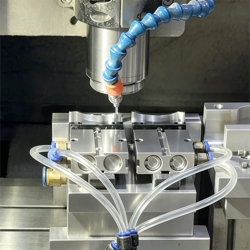
Buyers searching for ISO grade CNC machining usually want one number: which grade a mill or a lathe holds in ordinary production. That answer is the top half of the table below, IT8 to IT10 on a standard finishing pass.
The second table worth keeping is the capability map. These ranges are typical production capability, not laboratory records. A skilled machinist fighting for one dimension on one setup can do better; nobody holds the lower end of these ranges across a batch of 2,000 parts.
| Process | Typical IT grades it holds | What that means on a Ø30 feature |
|---|---|---|
| Lapping and honing | IT4 to IT6 | 6 to 13 micrometers |
| Precision grinding | IT5 to IT7 | 9 to 21 micrometers |
| Fine boring on a machining center | IT6 to IT7 | 13 to 21 micrometers |
| Reaming | IT8 to IT9 | 33 to 52 micrometers |
| Turning, finishing pass | IT8 to IT10 | 33 to 84 micrometers |
| Milling, finishing pass | IT8 to IT10 | 33 to 84 micrometers |
| Broaching | IT7 to IT8 | 21 to 33 micrometers |
| Drilling | IT11 to IT13 | 130 to 330 micrometers |
| Sheet metal cut and bent | IT12 to IT14 | see our sheet metal tolerance guide |
| Die casting | IT12 to IT14 | 210 micrometers and outward at Ø30 |
Read the drilling row before you put ±0.01 mm on a hole that comes straight off a drill body. A twist drill does not hold IT7 and asking it to is not a tolerance problem, it is a missing process step. The hole needs a reamer or a boring pass afterwards, and that decision belongs on the drawing, not in the shop.
Where ±0.01 mm Sits on This Scale
We advertise ±0.01 mm, and we deliver it, but it is worth being honest that ±0.01 mm is not a fixed difficulty. It changes grade as the feature gets larger:
| Feature size | Total band for ±0.01 mm | Nearest ISO grade | Comment |
|---|---|---|---|
| Ø10 | 20 micrometers | between IT7 (15) and IT8 (22) | comfortable for fine turning or fine boring |
| Ø30 | 20 micrometers | IT7 (21) | our default working band, one setup, standard tooling |
| Ø80 | 20 micrometers | marginally wider than IT6 (19), still well inside IT7 (30) | possible on selected features with fine boring and controlled measurement, not standard production |
| Ø150 | 20 micrometers | between IT5 (18) and IT6 (25), effectively IT5 | precision grinding and jig boring territory: temperature control, repeated measurement, and real scrap risk |
So when a drawing asks for ±0.01 mm across every dimension on a part that is 150 mm long, the drawing has asked for close to IT5 everywhere. That is a precision grinding and jig boring specification, priced four to six times the general tolerance baseline in the cost table below. It does not fail because we are not careful, it fails because the process that produces it costs money in a way nobody budgeted, and the honest answer at quote stage prevents a disaster at inspection.
For the features where ±0.005 mm genuinely is needed, and there always are two or three, we hold it on short features with fine boring or grinding and we say so on the quote. That number with its context is set out in our CNC machining tolerance guide.
What a Grade Costs
Below is our own quoting experience expressed as an index, with the general tolerance band of IT9 as the baseline of 1.0. These are our numbers on our machines, not a universal law, but the shape is what we would defend in any negotiation: each grade tighter multiplies again rather than adds.
| Grade requested | Cost index relative to IT9 | What changes on the floor |
|---|---|---|
| IT10 to IT9 | 1.0 | nothing, this is what standard tooling already gives |
| IT8 | 1.2 to 1.3 | dedicated finishing pass, sharper tool management, slower feeds |
| IT7 | 1.4 to 1.7 | fine boring or grinding on the feature, in-process gauging, cooled parts |
| IT6 | 2.2 to 2.9 | second operation, thermal soak before finishing, often 100 percent inspection |
| IT5 | 4 to 6 | precision grinder or jig borer, fixture dedicated to one feature, measurement between passes |
The multipliers get their drama from three things, in order: the extra operation, the inspection time, and the scrap. A feature at IT7 might get away with a better insert and a slower finish pass. The same feature at IT6 usually needs to leave the machining center for a grinder, which means another fixture, another handling step, another queue and another chance to damage a nearly finished part. At IT5 you add temperature control on top, because the part and the gauge have to agree about what 20 degrees means before anything else matters.
Now apply that to the chassis from the opening. Eighty four dimensions at IT4 would have meant every face ground, under metrology conditions, with scrap running well into double digits. Six dimensions at IT7, everything else left on ISO 2768 class m, and the part became an ordinary job that any competent shop can quote. The design intent never changed, which is why we offer a free DFM review on drawings like this before anybody quotes anything.
Two Ways to Put a Grade On the Drawing
There are only two, and mixing them carelessly is where arguments start.
The first is the general tolerance block. ISO 2768-1 gives you four classes for linear dimensions, f, m, c and v, plus geometric classes H, K and L, and you write something like ISO 2768-mK in the title block. Class f sits close to IT12, class m is looser still, and every unmarked dimension inherits it. This handles the eighty percent of features that only have to exist in roughly the right place, and we cover the class letters in detail in our tolerance guide.
The second is the per-feature callout, which is where an ISO tolerance grade actually shows up in writing. Three forms occur in practice:
- A tolerance class symbol, Ø25 H7 or Ø25 g6. This is the most information per character of any notation ever invented, and it is what every fit table is indexed by.
- An explicit bilateral tolerance, 25.000 to 25.021, or 25 plus 0.021 minus 0.000. Useful when design has already done the arithmetic and does not want us redoing it.
- An explicit symmetric tolerance, Ø25 ±0.01. Legal, but it throws away the fit information and it forces a symmetric band onto features where the process would rather be asymmetric.
If it is a fit, write the class symbol. If it is not a fit, write a bilateral number or let the general block carry it. Writing ±0.01 on a shaft that has to rotate in a hole is the most common reason we end up asking a customer to reissue a drawing.
Choosing a Grade, Step by Step: One Bearing Bore
Here is the sequence we actually run when a single feature matters, using a Ø35 mm bearing seat in an aluminum robotic joint housing as the example.
- Establish what it does. The bearing outer ring either rotates in the bore under load, or it sits still while the inner ring turns. If it rotates, it needs interference, because a clearance fit lets the ring creep, and creeping means fretting, ovality and noise. If it sits still, a clearance fit is better, because the bearing can be replaced in service without a press. That decision, not the machine, sets everything after it.
- Write the fit, not adjectives. Rotating outer ring becomes Ø35 H7/p6; stationary outer ring becomes Ø35 H7/h6. Both are calculated out in our shaft and hole fits guide. In the size step above 30 to 50 mm, IT7 is 25 micrometers, so the bore is 35.000 to 35.025. That band is slightly wider than the ±0.01 mm window we quote on critical features, which is why H7 at this size is routine for fine boring.
- Check the grade against a real process. IT7 does not come off a drill body. The route is drill, then fine boring to size, which is the honest difference between a drawing that says Ø35 H7 and a drawing that says Ø35 ±0.01 with no process implied. Parts like this run on our 5-axis and machining centers, described in our five-axis capability page, and the joint housings themselves are covered in our robotics CNC parts guide.
- Add the geometric controls separately. A press fit in a bore that is tilted 0.1 degrees beats the worst possible size error, because the bearing goes in crooked and there is nothing the fit can do about it. Perpendicularity to the datum face and coaxiality between the two bearing seats belong next to the size callout, with datums named, not implied.
- Set the surface finish that protects the fit. We take the seat to around Ra 1.6 micrometers. A rougher seat leaves peaks that flatten the first time the bearing is pressed, and the interference you paid for disappears into the surface texture. The finish arguments are set out in our surface roughness guide.
- Decide how it gets proven. The size is measured with a bore gauge or on the CMM, the form is measured separately, and everything appears on the first article inspection report together with the measured interference on the mating shaft, because a fit is a property of two parts, not one.
Six decisions, one feature, and not one of them is helped by writing ±0.005 mm in the title block.
A Grade Controls Size, Not Shape or Position
This is the mistake that costs the most and it deserves its own heading. Putting H7 on a bore tells everybody how big the bore must be. It says nothing about whether the bore is round, whether it is straight, or whether it is in the right place, at the right angle, relative to the datum structure.
A Ø25 H7 bore, 125 mm deep, made in a 200 mm tall housing can be perfectly H7 at every point along its length and still have drifted 0.3 mm out of position by the bottom. Everything in specs is in tolerance and the assembly does not go together. The tool for that is a positional tolerance with datums and material condition modifiers, which we work through in our GD and T true position inspection guide.
The practical rule we apply when reviewing a drawing: size controls size, form controls shape, position controls location. Ask for the three separately, not once for all three, because asking for them together is how a bore ends up needing IT5 roundness to satisfy a positional requirement nobody wrote.
Temperature: The Band You Lose Before Cutting Starts
ISO 1 fixes the reference temperature for dimensional measurement at 20 degrees Celsius. Nobody machines at 20 degrees in a Guangdong summer, and neither does anyone inspect there, so every measurement carries this correction whether or not anyone writes it down.
Thermal expansion tells you how much. Aluminum grows about 23 micrometers per meter per degree; steel around 12; stainless closer to 16; titanium near 8.6. Take a 100 mm aluminum housing, machined at 30 degrees and measured immediately: it is 0.1 meter times 23 micrometers per meter per degree times 10 degrees, which is 23 micrometers longer than it will read at reference. In the 80 to 120 mm size step, IT7 is 35 micrometers, so the thermal error alone has consumed about two thirds of your tolerance band before a single number is recorded.
We handle this on anything at IT7 or tighter by soaking parts to the inspection temperature before measurement, recording the part and gauge temperature on the first article report, and letting the fixture mass absorb most of the cutting heat before the finishing pass. It costs time, and it is one of the items in that cost table above. It is also why shops that quote ±0.01 mm without saying anything about temperature are quoting something they do not control.
Proving It: Uncertainty and the Ratio Rule
There is an old rule in metrology, the gagemaker rule of ten to one: the measuring instrument should be ten times more accurate than the tolerance being checked. Modern practice accepts a four to one ratio, expressed as test uncertainty ratio, and applied to the expanded uncertainty of the whole measurement rather than the resolution of the gauge.
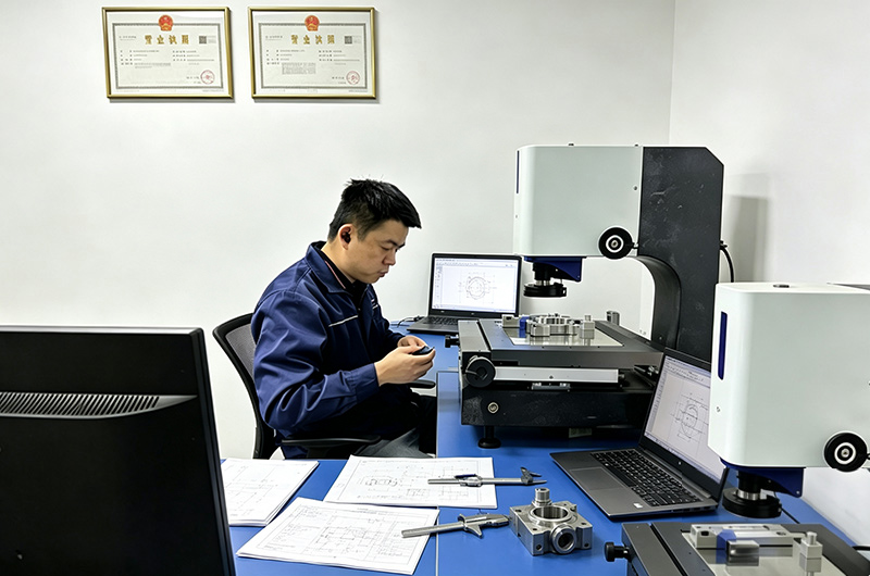
For a typical shop-floor coordinate measuring machine, the ISO 10360-2 specification for length measurement error runs somewhere around 2.5 micrometers plus roughly one micrometer per 300 mm of measured length. On a 100 mm feature that is about 2.8 micrometers of instrument uncertainty, against an IT7 band of 35 micrometers, which is roughly twelve to one. Comfortable. Do the same calculation against an IT5 band at that size, around 15 micrometers, and you are under six to one, still workable but you now care about fixturing repeatability, probe strategy and the number of points being averaged, which we cover in our CNC inspection methods guide.
When you ask for a grade below IT6, ask at the same time how it will be measured. A tolerance that cannot be measured is not a specification, it is an intention. The definition of the meter behind all of this comes from the international system of units, and the practical work behind industrial measurement is well covered by the metrology program at NIST.
Stacks: Worst Case Against Root Sum Square
An IT grade on each of four features does not tell you what happens at the end of an assembly, because tolerances accumulate. There are two ways to add them and they give very different answers.
Worst case simply adds them. Four features each contributing plus or minus 0.05 mm from the general tolerance block give a possible variation of 0.40 mm at the far end of the chain. Nothing is wrong, everything is in tolerance, and yet something may not assemble.
Root sum square, usually written RSS, combines them as the square root of the sum of squares. Same four features: the square root of four times 0.05 squared, which is 0.10 mm, a quarter of the worst-case number.
The tempting part is obvious. The dangerous part is that RSS is only valid if each contributing dimension is controlled by a process held near the middle of its band, with the variation known and monitored. If any single dimension in the chain is produced at the edge of its tolerance, or the process is not centered, the worst-case answer is the true one. We use worst case unless a customer gives us capability data that justifies RSS, which is the sort of thing a proper quality system already produces and which our IATF 16949 explanation walks through from the other side. In practice this means: give us tolerance and capability data in the RFQ, because it changes the recommended grade.
What Buyers Actually Ask Us
Can you hold ±0.01 mm across the whole part? On features up to about Ø30, yes: ±0.01 mm is a 20 micrometer band, essentially IT7, and it is our normal working band. Beyond roughly Ø80 the same number stops being a machining tolerance and starts being a metrology problem, so ask per feature rather than per drawing.
Do I need to write the IT grade itself on the drawing? Usually not. Write the fit symbol or the bilateral limits, and let the grade live behind them. The grade is the standard's internal scaffolding; H7 is what goes on the print.
Is a tighter grade always better? No. Every grade costs again, not additively. Tightening something that mates is money well spent; tightening something that only has to clear is money spent to raise the scrap rate.
Can you quote to ISO 2768 alone? Yes, and for most parts that is the right answer for eighty percent of features. But the general block cannot carry a fit, a bearing seat or a shaft journal, because those need both members described.
Why did two shops quote different amounts for the same tolerance? Usually because one has read the size steps and the other has not, or because one has included a grinder and the other intends to fight it on the machining center. Ask both how they will make the tightest feature and how many pieces they will measure, and the price gap will explain itself every time.
What happens if the grade turns out to be impossible in production? We say so at the quote, which is what free DFM is for. It is far cheaper for everyone to move a tolerance during quotation than to discover it at first article.
FAQ: ISO tolerance grades
Do I have to write IT7 on the drawing, or is H7 enough?
Write H7. The grade is already inside the class symbol, so naming both is redundant, and every fit table is indexed by the symbol rather than by the grade number. We use the grade when we talk to each other about process capability, and we use the symbol when we talk to the drawing.
Can you hold IT7 on a production batch, or is it a development-only number?
IT7 is routine production for us on features up to about Ø80 with fine boring, not a special case we fight for on one piece. It is a 21 micrometer band at Ø30 and 30 micrometers at Ø80, and a batch is a question of tooling and inspection discipline rather than of machine capability. But IT7 at Ø10 is 15 micrometers and at Ø80 it is 30 micrometers, so the same ±0.01 mm request lands at different grades on different features. It is safer to speak in grades and fit symbols than in a single symmetric band for the whole drawing.
Which ISO standard defines tolerance grades?
ISO 286-1 defines the basis of tolerances, deviations and fits, including the tolerance unit and the grade multipliers. ISO 286-2 contains the numerical tables of standard tolerance grades and limit deviations for holes and shafts. ISO 2768 parts 1 and 2 cover general tolerances for features with no individual tolerance indicated, which is the other half of any drawing.
What tolerance grade can CNC machining normally hold?
As a working range, machining centers hold IT8 to IT10 in ordinary production, IT7 routinely with fine boring or dedicated finishing passes on features that matter, and IT6 when the feature justifies a second operation or grinding below that. Anything tighter than IT6 needs lapping, honing or jig boring and should be discussed before the drawing goes out.
How does an ISO tolerance grade affect cost?
Roughly by a factor per grade rather than by a fixed amount. Moving from IT9 to IT8 costs on the order of twenty percent more; IT7 runs forty to seventy percent over baseline; IT6 can be two to three times baseline because it usually adds an operation and full inspection; IT5 is commonly four to six times because it adds dedicated tooling, thermal control and repeated metrology.
Do tolerance grades apply to form and position as well?
No. An IT grade governs size only. Roundness, straightness, flatness, angularity and position are geometric characteristics, covered by GD and T symbols against datums. We often see drawings where a tight size grade was used to imply a geometric requirement, and it rarely works, because a bore can be exactly H7 at every station and still be in the wrong place.
Should I use ISO 2768 or call out individual tolerances?
Both, deliberately. Put ISO 2768 followed by a class letter in the title block to cover everything with no individual tolerance, then call out fits, bearing seats, sealing faces and anything with a functional clearance or interference individually. What you should not do is leave the general block off and rely on a blank ± value for every dimension.
Let's Talk About the Numbers On Your Print
Send us the drawing as it stands, even if the tolerance block is a guess. We will read the grades against the processes that actually have to make them, tell you which three features are driving the price, and show you what happens to the quote if those features move one grade in either direction. Sometimes the answer is that nothing should change and the part is correctly specified; quite often there are thirty percent hiding in a title block note.
Either way you get the same thing we give every customer: free DFM on the drawing, a quotation within 24 hours, ±0.01 mm on the features we commit to, and a machine shop in Dongguan with more than 200 CNC machines behind the commitment. Send us the drawing and we will answer in plain language, including telling you when a tolerance is tighter than the part needs. Reach us on WhatsApp at +86 17620300785 or by email to gongtianbao@xhlmarketing.com.