
A German audio equipment maker sent us photographs before they sent us a drawing. Their 2 mm 304 stainless front panel, 420 × 260 mm, was arriving with the outline right and the hole pattern wrong: six M4 clearance holes that had to drop over studs on a machined subplate, drifting by up to 0.35 mm at the corners of the pattern, brown oxide edges that had to be scrubbed before powder coating, and roughly 0.6 mm of bow across the long axis that no shim at assembly could absorb.
The supplier was not careless. They were cutting with oxygen on a CO2 machine, running one nesting layout across the panel family, and applying a single kerf offset to every hole. Each of those is ordinary shop practice, and each one costs money at assembly.
We changed four things: nitrogen instead of oxygen, a separate kerf offset class for holes instead of a global one, a re-nest that put the vent pattern on a common cut line, and a short CNC pass on the six holes that actually controlled the fit. The hole pattern went from ±0.20 mm to ±0.05 mm, the scrub step disappeared, and the panel came off the brake flat. Gas cost went up; finishing, scrap and assembly labor went down by more.
*(Composite example; details changed.)*
That job is the reason this guide exists. Our sheet metal fabrication guide compares laser against punch and waterjet at the process level, which is where to start if you are still choosing a method. This page stays inside the laser: what the beam does to the metal, what the assist gas does to the edge, where kerf and taper eat your tolerances, and how each decision lands on the unit price. It is for the engineer who already knows they need sheet metal laser cutting and wants to see what the supplier is deciding on their behalf.
What a fiber laser actually does to the metal
A laser does not cut. It melts a narrow track and a coaxial gas jet blows the melt out of the bottom of the sheet. Everything about edge quality, tolerance and cost follows from three quantities: the wavelength of the light, the power density at the focused spot, and how reliably the molten material leaves the kerf instead of refreezing on the underside.
Wavelength and absorption: why fiber won
Two technologies dominate metal cutting, and they differ by a factor of ten in wavelength.
| Attribute | Fiber laser | CO2 laser |
|---|---|---|
| Wavelength | 1.06 to 1.08 µm, typically 1070 nm | 10.6 µm |
| Absorption on cold steel | Materially higher, and rises steeply once a melt pool forms | Low until the surface melts, then unstable on reflective alloys |
| Focused spot | Small, high power density | Larger at equal optics, lower density |
| Speed on 1 to 3 mm sheet | Two to five times faster at equal rated power | Slower |
| Thick plate | Competitive to 20 mm and beyond on modern high power units | Historically the thicker-plate choice |
| Wall-plug efficiency | Roughly 25 to 35 percent | Roughly 5 to 10 percent |
| Reflective metals | Workable with the right pierce strategy | Poor, with real back-reflection risk |
| Non-metals | Poor, the beam passes through many plastics | Strong, absorbs well in organics |
Absorption is the whole argument. At 1 µm, cold steel takes in several times more of the incident energy than at 10.6 µm, and once a melt pool exists the absorptivity climbs steeply. That is why a fiber source pierces reliably on stainless and aluminum where an older CO2 source hesitates or trips on reflected light, and why a smaller focused spot compounds the advantage. Add the efficiency gap and you get the outcome every buyer has noticed: fiber laser cutting is now the default quote for stainless and aluminum under roughly 8 mm, and CO2 is a legacy process kept alive by installed base and non-metals.
CO2 survives on clear plastics, on very thick plate in older shops, and on legacy part families whose kerf width and edge color belong to the original validation. We tell you on the quote when a part would move from one source to the other, because a different source on the same DXF is not the same part.
Kerf width and kerf compensation
The kerf is the material the beam removes. It is not a line, it is a slot, running roughly 0.1 to 0.4 mm on sheet metal depending on material, thickness, gas and focus, widening with thickness. Anything you dimension on a laser cut sheet metal part is measured after that slot has gone, so the programming offset decides your finished size.
| Material and thickness | Assist gas | Typical kerf | Comment |
|---|---|---|---|
| 1.0 mm stainless 304 | Nitrogen | 0.10 to 0.15 mm | Clean, near parallel walls |
| 2.0 mm stainless 304 | Nitrogen | 0.15 to 0.20 mm | Our everyday production case |
| 3.0 mm cold rolled steel | Oxygen | 0.20 to 0.25 mm | Wider because the reaction adds heat |
| 6.0 mm cold rolled steel | Oxygen | 0.25 to 0.30 mm | Taper starts to show on the wall |
| 2.0 mm aluminum 5052 | Nitrogen | 0.20 to 0.25 mm | Reflectivity and conductivity widen the track |
| 8.0 mm cold rolled steel | Oxygen | 0.30 to 0.40 mm | Hole sizes now measurably top versus bottom |
Compensating the kerf, and what it does to hole sizes
The CAM system offsets the cut path by half the kerf: outward on an external contour so the part reaches nominal, inward on a hole so the hole opens to nominal. The failure mode we see on incoming programs is one global offset applied to every feature on the sheet.
Kerf is not constant across a nest. Holes are cut slower and with more dwell than long profiles, corners decelerate and dump heat, and pierce conditions differ from a through-cut, so holes cut slightly wide relative to the profile offset. One global offset leaves external dimensions near nominal and holes undersized. On the panel above, the holes ran 0.10 to 0.15 mm small, consistently.
We run separate offset classes: one for the external profile, one per hole diameter band, one for slots. We cut a coupon from the actual sheet lot, measure it, adjust, then release the nest. If you are evaluating a supplier, ask what offset they applied and whether they verified it on a coupon. It takes ninety seconds to ask, and it is the difference between a hole pattern that assembles and one that nearly does.
Assist gas: the decision that costs real money
Assist gas does two jobs when you are laser cutting sheet metal: it blows melt out of the kerf, and it either protects the cut face from oxygen or deliberately adds oxygen to the reaction. That second job is a fork in the road, and it is the most under-discussed line on a laser quote.
Nitrogen versus oxygen: what you are actually buying
Nitrogen is inert. The cut face comes out bright and oxide free, weldable without grinding, and ready for powder coating after nothing more than a deburr. It is slower than oxygen on carbon steel and it is consumed at high pressure, so it costs more per part.
Oxygen is not just a purge, it is a reactant. On carbon steel the iron burns, and that reaction supplies much of the cutting energy, so feed rate rises and the gas is cheaper. The price is a magnetite layer on the cut face, which has to come off before welding, because it causes porosity and lack of fusion, and before powder coating, because it undermines adhesion and telegraphs as a dark line.
On stainless the decision is not cosmetic. Chromium at the cut face combines with oxygen, the edge loses what makes it stainless, and an oxygen-cut edge will rust bloom in humidity even under a powder coat, unless abraded back and passivated. We do not cut stainless with oxygen for anything visible, washed, or coastal. Aluminum is different: the oxide is hard and thin, nitrogen is standard, and the argument there is about dross.
| Assist gas | Relative gas cost | Speed, 3 mm carbon steel | Cut face | Prep before welding | Prep before coating | Best for |
|---|---|---|---|---|---|---|
| Nitrogen | Highest | Baseline | Bright, oxide free | Deburr only | Deburr only | Stainless, aluminum, weld prep, cosmetic parts |
| Oxygen | Lowest | Up to 30 to 50 percent faster | Dark magnetite layer | Grind or blast | Grind or blast | Carbon steel, hidden edges, structural parts |
| Air | Near zero, compressor only | Close to oxygen on thin sheet | Light straw to grey oxide | Grind | Grind or blast | Thin carbon steel that gets blasted anyway |
Air cutting, and when it is fine
Air cutting runs clean, dry compressed air through the same nozzle. Gas cost essentially disappears and speeds on thin carbon steel are competitive with oxygen, so it is a legitimate choice for 1 to 3 mm carbon steel that will be blasted and coated regardless. It is wrong for stainless, because oxygen and nitrogen at temperature damage the corrosion resistance you paid for, and wrong for weld preparation. It also depends entirely on air quality: oil or water carryover from a shop compressor lands on the cut face and then under your coating. Ask about filtration and dryness before you accept it.
The way we frame the trade: the nitrogen surcharge on a panel that size is measured in cents, while a manual scrub before coating is measured in minutes of labor. Minutes beat cents, which is why our default quote on stainless and aluminum carries nitrogen with no secondary edge prep.
Heat-affected zone, dross and edge taper
How much HAZ matters, and when it does not
The heat-affected zone on a laser cut edge is narrow, tens of micrometers to a couple of tenths of a millimeter on thin sheet, and far smaller than plasma or flame produces. For most parts it is irrelevant. It stops being irrelevant in four situations.
Stainless sensitization is the first: the steel around the cut loses local chromium, and the symptom is tea staining along the edges months later. Aluminum is the second. 6061-T6 is artificially aged, and the band next to the cut sees temperatures that overage it, so local yield strength drops. That matters when a load path runs near a cut edge, and it shows as a halo after anodizing, since the softened band takes dye differently. Our anodizing guide covers why 5052 hides this and 6061 does not. Third is forming: a cut edge on the outside of a tight bend can crack. Fourth is coated stock, where zinc vaporization at a galvanized edge causes weld porosity.
For everything else, a bracket in a dry enclosure, a mounting plate, an internal chassis, HAZ is a specification worry rather than a part failure.
Dross, taper and edge squareness
Dross is melt that refroze on the underside instead of leaving the kerf. Soft dross wipes off. Hard dross needs grinding, and it is a symptom worth chasing: low gas pressure, a worn nozzle, a dirty lens, focus in the wrong place relative to the sheet, or a feed rate off the sweet spot. If every part in a batch has hard dross on the same edge, the setup is wrong, not the material.
Taper is what buyers never budget for. The kerf is not a parallel slot: it is wider at the top than the bottom, by roughly 0.02 to 0.10 mm on thin sheet and more as thickness grows, so the diameter on the top face is not the diameter underneath. ISO 9013 grades this separately, as perpendicularity or angularity *u*, with edge roughness graded as *Rz5*, and the full grading sits in our sheet metal tolerance standards guide. For your drawing: if a hole diameter is functional, say which face it is measured on.
The drag lines on the cut face are the third edge characteristic, and what people mean by laser edge roughness. We cover measurement separately in the surface roughness guide, but for quoting: a nitrogen cut on 2 mm stainless is a bright face needing no further work, and an oxygen cut on 6 mm steel is a striated, oxide-covered face that always does.
Feature limits: holes, slots, webs and corners
Minimum hole diameter scales with thickness
The rule of thumb the whole industry works to is that a round hole should be at least 1.0 × material thickness in diameter, and that 1.5 × thickness is where quality and cycle time both become comfortable. Below 1 × T the melt cannot clear cleanly, dross sticks inside the hole, and roundness suffers.
| Material thickness | Minimum hole Ø | Recommended hole Ø | What happens below the minimum |
|---|---|---|---|
| 1.0 mm | 1.0 mm | 1.5 mm | Dross inside the hole, ragged exit |
| 1.5 mm | 1.5 mm | 2.5 mm | Slow pierce, heat build-up |
| 2.0 mm | 2.0 mm | 3.0 mm | Roundness drifts, exit burr grows |
| 3.0 mm | 3.0 mm | 4.5 mm | Consistent dross, taper visible |
| 4.0 mm | 4.0 mm | 6.0 mm | Piercing dominates cycle time |
| 6.0 mm | 6.0 mm | 9.0 mm | Consider drilling instead |
When a hole is smaller than the thickness, do not force the beam: drill it, punch it, or move it to a post-cut operation. A 2 mm hole in 3 mm stainless is a drilling job, and treating it as one usually removes cost rather than adding it. Deciding which features belong to the laser and which belong to a second operation is the core of a proper DFM analysis before quoting, and it is free when you send us the model.
Slots, webs and sharp corners
Slots want a width of at least 1.0 × T and are happier at 1.2 to 1.5 × T. Length matters too, because a slot longer than about eight times its width starts to close up from heat. If you need a long ventilation slot, break it into two shorter slots with a bridge.
Webs between adjacent cutouts are where hole patterns quietly go wrong. Keep at least 1.0 × T between two features, and 2.0 × T if either is positional, because thin webs warp under the beam and drag the neighboring hole off location. Keep holes at least 1.0 × T from the part edge, 2.0 × T preferred.
Sharp internal corners are the last trap. A laser can notionally produce a near-zero radius, but the axis decelerates into the corner and the dwell rounds it. Put a radius of at least 0.5 × T on internal corners, and 1.0 × T where the corner is load-bearing or cosmetic. Watch small islands too: a fragment of skeleton surrounded by cut lines will heat, lift and collide with the head.
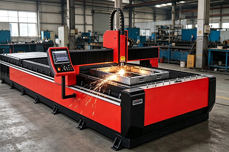
How thick can we cut: carbon steel, stainless, aluminum, brass, copper
Steel, stainless and aluminum
Capability is not a single number per material. It is a band where the edge is still good, then a band where the part is cuttable but slow and the edge quality is a compromise.
| Material | Comfortable production band | Cuttable but slower | Preferred gas | Notes |
|---|---|---|---|---|
| Cold rolled and hot rolled mild steel | 0.5 to 12 mm | 12 to 25 mm | Oxygen or nitrogen | Oxygen is fast and cheap; nitrogen when the edge welds or coats |
| Stainless 304 and 316 | 0.5 to 8 mm | 8 to 12 mm | Nitrogen | Oxygen costs you corrosion resistance at the edge |
| Aluminum 5052 and 6061 | 0.5 to 6 mm | 6 to 8 mm | Nitrogen | Reflective, conductive, dross-prone as thickness grows |
| Galvanized steel | 0.5 to 6 mm | 6 to 10 mm | Nitrogen | Zinc vapor needs extraction and complicates welding |
| Brass C260 and C360 | 0.5 to 4 mm | 4 to 6 mm | Nitrogen | Zinc fume; leaded grades raise handling questions |
| Copper C110 | 0.5 to 2 mm with the right setup | Above that, specialist | Nitrogen | See the reflectivity note below |
Brass and copper: the reflectivity problem
Copper separates shops that own a laser from shops that can cut copper. At room temperature copper absorbs only a small fraction of 1 µm light and reflects nearly all of it, so the beam bounces until a melt pool forms. The transition is abrupt, the reflected energy travels back up the path that delivered it, and a machine without back-reflection protection can be damaged in a fraction of a second. That is why many suppliers quietly decline copper, and why a busbar RFQ deserves a conversation rather than a checkbox.
Brass is more forgiving, because the zinc changes absorption and thermal behavior, and free-cutting grades cut cleanly up to a few millimeters, at the cost of zinc fume and, on leaded grades, handling rules some customers will not accept. Pure copper above roughly 2 mm is better produced by waterjet or machining, and we will say that on the quote rather than sell you a marginal laser job.
Two related cases catch people out. Polished or mirror-finish stainless reflects far more than mill finish, so the cosmetic face you specified changes the cutting parameters, and PVC-coated sheet cuts well with the film on but burns back at the cut edge and adds its own fume. If a supplier never asks about finish or coating, they are quoting the material in the drawing, not the material on the pallet.
Laser cutting tolerances we will put in writing
Here is the band we commit to on cut features, in the flat, on a properly nested and clamped sheet, measured at room temperature.
| Material thickness | Profile tolerance | Hole diameter tolerance | Hole-to-hole within one nest |
|---|---|---|---|
| 0.5 to 1.0 mm | ±0.05 mm | ±0.05 mm | ±0.05 mm |
| 1.0 to 2.0 mm | ±0.08 mm | ±0.05 to 0.08 mm | ±0.05 mm |
| 2.0 to 3.0 mm | ±0.10 mm | ±0.08 mm | ±0.08 mm |
| 3.0 to 6.0 mm | ±0.15 mm | ±0.10 mm | ±0.10 mm |
| 6.0 to 10 mm | ±0.20 to 0.30 mm | ±0.15 mm | ±0.15 mm |
| Above 10 mm | ±0.30 mm and up | ±0.20 mm and up | Taper dominates the result |
Three caveats belong with that table. It assumes the sheet is flat and clamped, because a sheet with residual coil set moves as it is cut, and that critical parts are nested away from the sheet extremities, where thermal growth shows up first on a 1.5 × 3 m table. And it is a cutting number, not a machining number: if a feature genuinely needs ±0.01 mm, we hold that by machining after cutting. Every millimeter below this band is bought with a second operation.
Why cut tolerance and bent tolerance are different numbers
This distinction resolves most "the parts do not fit" arguments. A dimension that lives entirely in the flat inherits the table above. A dimension that crosses a bend inherits the press brake instead: springback, thickness variation, tooling wear, and the K-factor used to unfold the flat. In practice a cut profile at ±0.05 mm becomes a formed flange at roughly ±0.25 to 0.50 mm, and a K-factor error of 0.05 alone shifts a flat pattern by a few tenths per bend.
So keep functional dimensions off the bend wherever geometry allows, and where it does not, either specify the feature in the formed state and machine it after forming, or design the joint to live inside the wider band. The derivation and the springback figures by alloy are in our bend allowance guide, and the classes for what the drawing should say are in the tolerance guide.
On hole patterns, write a position tolerance rather than coordinate ±. A coordinate callout of ±0.10 in X and ±0.10 in Y produces a square acceptance zone whose corner sits 0.141 mm from true position, and that corner is where assemblies fail. The ASME Y14.5 standard is the reference we dimension to when a customer names one.
Nesting, material utilization and where the laser stops paying
Nesting is the layout of parts on the sheet, and material utilization is usually the largest single line in the unit cost of a laser cut part. Sheet is bought by area and the skeleton is sold back as scrap at a fraction of what it cost, so a nest running at 60 percent throws away 40 percent of the material you paid for.
The lever buyers rarely pull is the outline itself. On one bracket family we reviewed, a 20 mm cosmetic flange and a decorative 10 mm corner radius were forcing the parts apart on the sheet. Relieving the flange to 12 mm and squaring one corner let two parts share a cut line and moved the nest from 61 to 69 percent: eight percentage points of utilization, or about 12 percent less material per part. That 1 mm of contour roughly covered the nitrogen surcharge, and changed nothing the assembly cared about.
Common-line cutting saves time as well as material, because one traverse separates two parts instead of two. Grain direction is the constraint that fights it: requiring bends to run perpendicular to the rolling grain prevents free rotation in the nest, which typically costs 3 to 10 points of utilization. Say it when it matters for a visible or load-bearing bend, and let it go where it does not. The wider unit-cost picture is in our CNC machining cost guide.
Where the laser stops being the cheapest route
Once a simple profile repeats more than a few thousand times a year, a stamping die pays for itself and the piece price typically drops by a factor of two to three, and the full break-even arithmetic belongs to our stamping versus laser cutting comparison. The steel that die is cut from decides how long it holds that price, which is what our stamping die material guide is about.
After the cut: deburring and the finishing sequence
Every laser cut leaves something on the edge, whether a soft dross bead of 0.02 mm or a hard burr of 0.10 mm. It is sharp, it interferes with fit-up, and powder coating will not hide it, because coating pulls back from a sharp edge.
The order we quote is: cut, deburr and break edges, form, weld, re-deburr or grind the weld zone, surface prep, coat. Deburring before forming stops the burr marking brake tooling or cracking on the outside of a bend, and oxide removal before welding is what prevents porosity, covered in more depth in the sheet metal welding guide.
Methods split by part. Vibratory finishing suits small parts and gives a uniform edge, but it can peen soft aluminum and round corners you wanted sharp. Through-feed belt and brush machines suit flat panels and give a repeatable edge break, which is what we run on parts like the panel above. Manual work is for cosmetics and is the least repeatable, while electropolishing on stainless removes the HAZ and free iron in one step.
Specify an edge break, not a feeling. "Break sharp edges 0.1 to 0.2 mm" is purchasable and measurable; "remove all burrs" is not, which is why two shops price the same deburr line differently. The options and costs are in our deburring guide, and the coating side in the finishing guide.
A composite example: what the change did to the numbers
This is the 2 mm 304 stainless panel from the top of the article, with the numbers attached.
*(Composite example; details changed.)*
| Item | Before, oxygen on CO2, one offset | After, nitrogen on fiber, class offsets |
|---|---|---|
| Hole pattern position | ±0.20 mm, 0.35 mm worst case | ±0.05 mm, verified on CMM |
| Hole diameter spread across one sheet | 0.15 mm | 0.04 mm |
| Edge preparation before coating | Manual scrub plus belt, about 6 minutes per part | Deburr only, about 0.5 minutes per part |
| Flatness after cutting | Roughly 0.6 mm bow | Under 0.15 mm |
| Scrap and rework rate | 9 percent | 0.8 percent |
| Assembly fit rate | 1 panel in 6 needed hand rework | No rework |
| Unit price index | 100 | 95 |
Four changes produced that. Nitrogen removed the oxide, the scrub step and the heat pattern that was bowing the panel. Separate offset classes per hole diameter band removed the systematic undersize. A re-nest with a common cut line on the vent pattern moved utilization from 61 to 69 percent, which roughly covered the nitrogen surcharge. And the six holes that controlled the fit were finished on a machining center after cutting, which is where a ±0.01 mm number honestly comes from. Front panels like this are most of our audio equipment work: the outline is fine, the pattern is not. At 420 × 260 mm the panel sits inside the 1000 × 500 × 300 mm envelope of our milling centers, so that was one short program; a part needing compound angles moves to a five-axis cell, which tops out at 750 × 650 × 500 mm of travel and a Ø500 × 400 mm part.
Nothing here needed exotic equipment. It needed somebody to treat the nest, the gas and the offsets as one decision instead of three defaults.
What to send with your RFQ, and what to demand back
Eight items get you a comparable quote inside 24 hours. Two of them, quantity and critical features, decide whether laser is the right process at all.
- Material, temper and exact thickness, plus surface condition: 304 2B at 2.0 mm, 5052-H32 at 1.5 mm, and whether the sheet arrives with PVC film, brushed finish or mirror polish.
- Geometry as a native model or clean DXF, closed contours, one file per thickness, units stated on the file, and the flat pattern if you already have one.
- Quantity as two numbers: the quantity on this order and the annual volume. The process answer changes with the second one, not the first.
- The features that matter, marked: which holes position the part, which edges mate, which surfaces are datums, and the mating part if you have it.
- Tolerances on those features only, plus a general class in the title block. The reasoning and the classes are in our tolerance guide.
- Edge requirements if you have them: will the edge be welded, powder coated, anodized, or left visible in a humid environment.
- The downstream operations, whether you will form and weld in house or expect us to, and the edge break you want after cutting.
- Inspection and documentation: first article, material certificate, coating certificate, RoHS or REACH statements, and the PPAP level if this is an automotive program.
What to demand back: first article and material certs
A first article inspection is worth exactly as much as the discipline behind it. Ours is measured on a real part from the released nest, unclamped, at room temperature, and reported against a ballooned drawing, because a part that measures good while still clamped can move when the clamps come off. The protocol is in our first article inspection guide.
Material certification is cheap insurance. Insist on mill certificate traceability to the heat or lot, since the difference between 304 and a look-alike grade is invisible on the part and obvious in a salt spray cabinet, and on programs running to IATF 16949 or ISO 13485 it is not optional.
Ruijin Fenghui has been doing this in Dongguan for more than 23 years, across 200+ CNC machines and a sheet metal shop that runs laser, brake, weld and finish under one roof. We quote within 24 hours, the DFM review is free, and the prototyping guide explains what changes when you only need five pieces.

FAQ: what buyers ask us
Can you really hold ±0.05 mm on a laser cut part?
On thin material in the flat, yes, that is our routine band up to about 1 mm. We do not extend it to formed dimensions, to thick plate, or to a hole measured on a face you did not specify. If your requirement is ±0.01 mm we will still take the job, but we will price a machining operation after cutting.
Why do my holes come out about 0.1 mm small?
Almost always a single global kerf offset. Holes are cut slower and hotter than the external profile, so the effective kerf is wider on them, and one offset value cannot serve both. We run a separate offset per hole diameter band and verify it on a coupon from the same sheet lot.
Is nitrogen worth the extra line on the quote?
For stainless, yes, without qualification. For carbon steel that will be welded or powder coated, usually yes, because it deletes a grinding step that costs more in labor than the gas costs in consumables. For a hidden structural bracket, oxygen is the better buy, and we will quote both if you ask.
Can you cut copper busbars?
Pure copper is possible in thin gauges on a machine set up for it, and we will tell you honestly where our limit is, because high reflectivity sends energy back up the beam path. Brass we cut routinely. Above roughly 2 mm of pure copper we usually propose waterjet or machining rather than sell you a marginal laser job.
The parts fit in the flat and do not fit after bending. What changed?
Nothing went wrong; the tolerance changed owner. A dimension crossing a bend inherits press brake variation, springback and the K-factor used to unfold the flat, so a profile at ±0.05 mm becomes a flange at roughly ±0.25 to 0.50 mm. Move the dimension off the bend, or specify the feature in the formed state.
Why is one shop 30 percent cheaper on the same DXF?
Usually three assumptions you cannot see in the price: oxygen instead of nitrogen, no deburr or edge break included, and a nest at 60 percent utilization instead of 68. None of that is cheating, and all of it lands on your dock rather than their invoice. Ask which gas and what utilization the price assumes.
What do you need from me to quote in 24 hours?
Material and thickness, a clean model or DXF, both quantity numbers, and the features that control fit. Send those four and we will come back with a price, a process routing and a DFM comment. Send the mating part too if the panel has to drop onto something.
References
- ASME Y14.5, Dimensioning and Tolerancing. ASME
- Metrology, calibration and measurement uncertainty. NIST
- Dimensional metrology guidance. National Physical Laboratory
- The International System of Units (SI) and the definition of the metre. BIPM
- Coordinate measuring machine technology. Zeiss Metrology
Conclusion
More than 23 years of cutting, bending and machining metal has convinced us that most laser problems are specification problems wearing a process costume. The gas, the offset class, the nest and the edge break are four decisions a supplier makes on your behalf every time you send a DXF, and all four are cheaper to argue about before the nest is released than after the first article lands.
We run sheet metal laser cutting alongside metal stamping, machining, welding and finishing in one Dongguan facility, with more than 200 CNC machines, ±0.01 mm on machined features and ±0.005 mm on critical ones, working to IATF 16949, ISO 9001 and ISO 13485. Send us the drawing, the material, both quantity numbers and the mating part if you have one. You get a quote inside 24 hours, a free DFM review that includes the nesting study, and a plain answer on whether laser is the right process or a die would serve you better. If the honest answer is that your panel would be cheaper stamped, we will say that too. Talk to our engineers and we will start on it today.