
A 3C customer sent us a bracket drawing last spring with a date code called out at 0.10 mm deep, sitting 1.2 mm from a 90 degree bend. We built the progressive die, ran 8,000 pieces, and watched the code disappear under a 12 micron nickel plate. The part passed every dimensional check. The mark did not read, and all 8,000 went back through a laser cell we had not budgeted, which is exactly the rework that marking on stamped sheet metal is supposed to prevent. Our mistake was not depth. It was treating a stamped mark like a milled one.
A stamped code survives plating when it is coined 0.25 to 0.35 mm deep, placed at least two times material thickness plus the bend radius from any bend, and flagged on the plating traveler. Codes shallower than 0.15 mm close over under 8 to 15 microns of zinc. Verify readability on plated parts, never on bare steel.
Why Marking on Stamped Sheet Metal Breaks the Rules for Machined Parts
On a milled part, marking is the last thing we do to a surface we already control. We hold ±0.01 mm as standard and tighten to ±0.005 mm where fit depends on it, so the pad under a laser mark sits where the drawing says. A stamped part is different: the mark is a forming operation that displaces metal and changes how the blank springs back.
The surface is never truly flat, since coil thickness drifts 0.02 to 0.05 mm across a lot and that moves the code in and out of the laser focal window. The geometry keeps moving too. In progressive die stamping, a code coined at station 3 can be bent or drawn by station 9, the strokes stretch with the metal, and a deep stamp in a thin section puts a stress riser where the part works hardest.
This is why metal component marking on stampings needs its own rules. Our machined part traceability requirements do not transfer cleanly, and we say so at quote stage rather than after first article.
In-Die Marking vs Offline Marking
The first decision is whether the mark belongs in the die at all. Here is how we compare them, using numbers from our own floor.
| Factor | In-die marking | Offline laser or dot peen |
|---|---|---|
| Up-front cost | One insert, $180 to $400, plus 30 to 60 minutes of setup | No cutting tooling, but a fixture per part at $250 to $700 |
| Speed | Zero added cycle time, the mark lands on a station already in the strip | 1.5 to 4 seconds per part, off-line, plus two handling steps |
| Flexibility | Poor, a code change means a new insert and a die pull | Excellent, the code changes in software between parts |
| Depth | Coined or embossed at 0.05 to 0.40 mm, displaces metal | Anneal 0.002 to 0.01 mm, engraving 0.02 to 0.15 mm, dot peen 0.05 to 0.30 mm displacement |
| When each wins | Fixed text or logo, long runs | Date codes, serials, 2D codes, pilots |
The arithmetic is simple. A fiber laser station costs us about $24 an hour all-in, and a small bracket takes 2.5 seconds to mark, so 40,000 pieces is 28 hours of floor time, roughly $670 plus handling. The in-die insert on that job was $260 plus 40 minutes of setup. In-die wins above roughly 15,000 pieces for a code that never changes. Below that, or with a serial, we mark off-line.
Press speed tips the scale: on high-speed stamping at 400 to 800 strokes per minute, each added station costs money per thousand.
Making the Code Survive Plating, Anodizing and Painting
Most marking plans fail at plating stamped components, and always the same way: coatings fill low spots first and bridge small cavities. A 0.10 mm mark under 12 microns of nickel loses about 12 percent of its depth to the plate alone, and more to edge rounding. So when marking steel parts headed for zinc, we coin deeper than most drawings ask.
| Coating | What happens to the code | What we specify instead | Realistic thickness |
|---|---|---|---|
| Zinc or zinc-nickel plate | Low areas fill first, shallow marks close over at 8 to 15 microns | Coined at 0.25 to 0.35 mm, marked before plating | 5 to 25 microns |
| Electroless nickel | Follows the contour, sharp edges round off fast | 0.30 mm minimum depth, wider strokes | 5 to 15 microns |
| Type II anodize, aluminum | Oxide grows both ways, contrast depends on dye | Laser before anodize, or mask and laser after | 8 to 20 microns |
| Hard anodize | Buildup buries fine strokes and kills contrast | Embossed code, post-anodize laser on flat faces only | 25 to 50 microns and up |
| Powder coat | Film bridges cavities and hides edges | Raised code at 0.40 mm, or a masked bare window | 60 to 120 microns |
| E-coat or wet paint | Thinner than powder, still fills a 0.10 mm mark | Coined at 0.20 mm minimum, checked on first articles | 15 to 35 microns |
Two rules hold across all of them: mark before coating whenever the film is thin enough to preserve contrast, and verify readability after coating, never before. Coding and marking on coated metal is where most plans fail, so the read test runs on plated parts from the first batch, because a code that scans on bare steel says nothing under zinc.

Corrosion is the second filter. For automotive underbodies and marine housings we check the marked area against the ASTM B117 hours the customer named. A laser mark that breaks the passive layer on stainless can start the rust, so on stainless steel stampings we prefer anneal marking, which darkens the oxide without removing it.
Where to Put the Mark on a Stamped Part
In marking on stamped sheet metal, location causes more rework than depth. Our standing rules:
- Keep the mark at least two times material thickness plus the bend radius away from any bend line, 4.5 mm on 1.5 mm steel with a 1.5 mm radius.
- Stay off the sheared edge. The burr zone runs about one material thickness in from the cut, and deburring deletes half the code.
- Mark only a face that stays flat through every later station. If the strip forms after station 5, station 3 is too early.
- Leave at least 1.5 mm of clean metal on all four sides of a Data Matrix, and give the scanner a clear line of sight. A code under a flange that mates flush reads on the bench and never on the line.
- Keep clear of weld zones. On assemblies headed for sheet metal welding, spatter ruins a code within 10 mm of the seam.
When the mark location is dimensioned, we work to the sheet metal tolerance guide rather than borrowing machining numbers, since a stamped blank will not hold ±0.01 mm across its full length.
Case: 40,000 Brackets and a Code That Would Not Scan
*(Composite example; details changed.)*
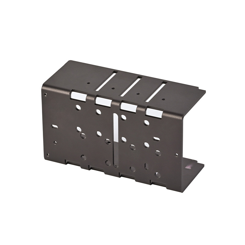
An automotive customer came to us with 40,000 zinc-plated steel brackets in cartons and a 2D code the line scanner read on about six parts out of ten. The stamping was fine. The code was coined at 0.12 mm, 1.0 mm from a bend, and the plater had never been told it existed.
We ran the numbers three ways. Hand-held re-marking was $0.42 per part, or $16,800, and it would break the plating. Scrapping and re-stamping ran about $11,000 plus six weeks. The die change was $310 plus 45 minutes of setup.
We changed the die instead. The code moved 6 mm off the bend, depth went to 0.30 mm, and we flagged that corner on the plating traveler. Read rate hit 100 percent on first article and 99.7 percent over three lots, for under $400.
What Buyers Actually Ask Us
Most often, buyers ask whether we can mark after the part returns from plating. We can, and sometimes we do, but a laser that cuts through zinc to reach steel has removed the sacrificial layer on that patch. In a dry 3C housing nobody cares. Under a car it matters, and we raise it before we quote.
Next is depth. A drawing reading "mark 0.1 mm deep" looks reasonable to a designer used to machined parts, but that is only about a quarter of the 0.40 mm we specify under powder coat. We stamp three depths on a sample strip, run it through the real coating line, and photograph the result.
Buyers also want a code that changes monthly. It can, with a rotary insert, but every swap is die time, and under 15,000 pieces a laser cell is cheaper. When a customer needs a permanent mark and cannot take a die pull, we lay out the permanent part marking methods and let the volume decide.
Dimensioning is the last one. Codes and location should be called out per ASME Y14.5, which you can review at ASME's Y14.5 page. A note saying "mark per sample" is not inspectable.
Frequently asked questions
Can you mark a stamped part after plating without hurting corrosion resistance?
Yes, though the mark removes coating locally. For indoor 3C and audio housings that rarely matters. For automotive and outdoor parts we coin before plating so the film covers the code, or we seal the marked area afterward.
How deep does a stamped mark need to be under powder coat?
Allow 0.40 mm of raised embossing against a 60 to 120 micron film. A coined 0.20 mm mark that reads clearly on bare metal will bridge over and lose its edges once powder flows.
Will a laser mark pass salt spray testing?
It depends on substrate and process. Anneal marking on stainless leaves the passive layer intact and generally meets the ASTM B117 hours set for the base material. Ablation through zinc or anodize does not, unless you seal afterward.
Can one progressive die produce a date code that changes every month?
Yes, with interchangeable or rotary inserts, but each change costs die setup time. Below roughly 15,000 pieces per code, off-line laser marking is cheaper.
Conclusion
We have done this for 23 years across 200+ CNC machines, and the pattern holds: codes fail because nobody connected the stamping decision to the finishing decision. Tell us the material, the coating, and where the part lives in service, and we will give you the depth, the location, and whether the mark belongs in the die. Quotes come back in 24 hours, DFM is free, and we work to IATF 16949, ISO 9001, and ISO 13485. Send the drawing. Talk to our team.