
Two inspection reports on the same batch of machined brackets, from two labs, disagreed by 0.06 mm on the same hole. Both labs were competent, both used calibrated CMMs, and both were measuring what the drawing said. The difference was that one had aligned to datum A as the mounting face and B as the long edge, in that order, and the other had aligned to the same two features in the opposite order. Every number downstream of that decision moved. (Composite example; details changed.)
We see this more often than we see a genuine machining problem. On the parts we quote, datum selection is usually the difference between a drawing that can be inspected and one that can only be argued about. It is also the cheapest thing to fix, because it happens before a single chip is cut.
We machine in Dongguan, more than 200 CNC machines, 23+ years, IATF 16949 and ISO 9001 and ISO 13485 in the quality system, quotations inside 24 hours with free DFM. This article is the set of rules we apply when we review the datum scheme on a customer's print, in the order we apply them.
What a Datum Is, and What It Is Not
A datum is a theoretically exact plane, axis or point from which other tolerances are measured. It is not the physical surface. The physical surface is the datum feature, and it is imperfect: flat to within 0.02 mm, perhaps, and never quite where the model says.
Inspection bridges the gap with a datum simulator, which in practice is a surface plate, a precision angle plate, a set of pins, or the CMM's alignment routine. The simulator contacts the high points of the datum feature, so the datum plane rests on the three highest points of a nominally flat face. That is why a face with a burr on one corner produces a completely different datum from the same face with the burr removed, and why deburring is a metrology operation as well as a handling one. The alignment itself, and how many points the program takes to build each plane, are covered in our CNC inspection methods guide.
Two consequences follow, and both matter in a shop. First, a datum feature has to be good enough to simulate: a rough cast surface with 0.5 mm of draft and a sand inclusion will not repeat. Second, the fixture has to touch the part where the simulator would, or the machined result and the inspected result will disagree even though both are correct within their own frames.
The Three Choices
Every datum scheme on a prismatic part answers the same three questions, and the order of the answers is the scheme.
Primary datum, three points, three degrees of freedom. The primary face stops translation along its normal and two rotations. It should be the largest, flattest, most stable face, and ideally the face the part actually sits on in the assembly. Three points define a plane, and they should be as far apart as the geometry allows, because the further apart they are, the less a local bump tilts the plane.
Secondary datum, two points, two degrees of freedom. The secondary feature stops the remaining two rotations: it fixes the part's rotation about the primary normal and one tilt. It should be a feature that actually locates in the assembly, usually a bore, a slot or a long edge.
Tertiary datum, one point, one degree of freedom. The tertiary stops the last translation, the slide along the secondary. It is usually a single hole or a short edge, and its job is to lock the part in the final direction.
Six degrees of freedom, six constraints, and the part is fully located. That is the 3-2-1 rule, and it holds for prismatic parts. It does not hold for a cylinder, where the axis itself is the datum and a pair of centers or a face-and-diameter combination does the work. Turned parts live in that second world, and a drawing that applies 3-2-1 logic to a shaft usually ends up with a datum scheme nobody can fixture.
The Rules We Actually Apply
Four rules, in order of how much trouble they save.
1. Pick the datum the part functions against, not the datum that is convenient to machine. If the bracket bolts to a frame on its back face, that back face is the primary datum, even if the front face is flatter and nicer. The inspection should reproduce the assembly condition, because the tolerance exists to protect a function that happens at assembly.
2. Pick a face big enough to simulate. A 4 mm wide ledge cannot carry a primary datum for a 200 mm part, no matter how flat it is. The rule of thumb we use is that the primary datum should span at least a third of the part's longest dimension, and the three contact points should be near the extremes of that span.
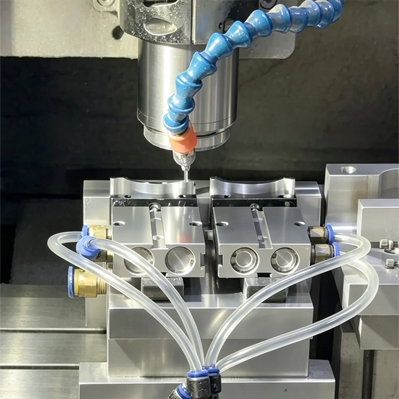
3. Machine the datum and the features it locates in one setup, or prove the transfer. If the datum face is machined in setup one and the bore in setup two, the relationship between them carries the fixture error of setup two. That is not automatically wrong, but it has to be known and budgeted. On our own parts we machine the primary datum, the locating bore and the critical pattern in a single setup wherever the geometry allows, and where it does not, we probe the datum after the re-clamp.
4. Do not use a rough surface as a datum without saying so. A cast boss, a saw-cut end or a flame-cut edge is a legitimate datum only if the drawing says the surface is unmachined and the tolerance is sized for it. When a drawing calls a raw casting face datum A and then holds a bore to ±0.02 mm from it, the requirement is not achievable, because datum A itself moves by more than the tolerance.
Where Datum Schemes Go Wrong
The failures we see are repetitive enough to list.
- Datum order flipped. Swapping A and B on a part whose two faces are not perpendicular changes every result. In the case at the top of this article that swap produced the 0.06 mm disagreement.
- Datum feature not accessible in the fixture. A datum on the inside of a pocket that the chuck covers cannot be used to align the part for the second operation.
- Datum on a feature that gets coated. Anodizing and plating change the datum surface. If datum A is an anodized face, the inspector is aligning to a surface that grew 0.01 mm after machining, and every dimension referenced to it shifts.
- Datum on a small boss or a thin rib. The simulator contacts the high points of a feature that deflects under clamp load, so the datum depends on how hard the part is held.
- Too many datums. A three-datum scheme plus a fourth and fifth datum usually means the designer did not decide which features matter. Extra datums do not add precision, they add negotiation.
- Datum symbols floating on a centerline. A datum attached to a centerline without a feature of size is not interpretable, and two inspectors will read it two ways.
Turned Parts: The Axis Is the Datum
On a shaft or a housing turned between centers, the datum is the axis established by the two centers, or by a face and a diameter. That changes the arithmetic. A diameter callout controls size and, through its own form tolerance, the axis position; a coaxiality or runout callout controls the relationship between two axes, and the inspection that proves it is worked through in our true position inspection guide.
The practical consequence is that the chucking method decides what the drawing means. A part turned in a three-jaw chuck and then flipped has two axes, not one, and the runout between them carries the jaw error. A part turned between centers, or held in a collet machined in place, has one axis for the whole operation.
This is why we ask, on any shaft with a runout callout tighter than 0.02 mm, how the customer intends to hold it in inspection. If the answer is a V-block on the bearing journals, we machine to that. If the answer is a chuck on the raw bar, the callout is measuring the chuck.
Our 4-axis machining guide covers the multi-setup case in more detail, and the shaft and hole fits guide works through how a datum shift changes an actual fit.
How the Datum Shows Up in the Price
Datum selection is not free. It sets the number of setups, the fixture, and the inspection time.
A part with one clean primary datum, machined in a single setup against a well-chosen three-datum scheme, is the cheapest version of itself. Add a requirement that a bore on the opposite face be positioned to 0.03 mm from a datum on the first face, and the part now needs either a second operation with a precision fixture or a five-axis machine that reaches both faces without re-clamping. Either way the price moves, and it usually moves by 30 to 60 percent, not by a few percent.
The reverse is also true and less often noticed. Many prints carry a datum scheme copied from a similar part, with a tighter relationship than the function needs. When we run the assembly stack and find the relationship is not critical, we say so in the DFM note, and the part gets cheaper without getting worse. That conversation is worth having before the drawing is released, not after the first article fails.
What We Ask For Before We Quote
Send the drawing, and we will read the datum scheme before we read anything else. Four things make that read fast:
- The functional interface, marked or described. One sentence is enough: "this face bolts to the frame, this bore takes the bearing".
- Which features are machined and which are as-cast or as-cut, because that decides what can be a datum.
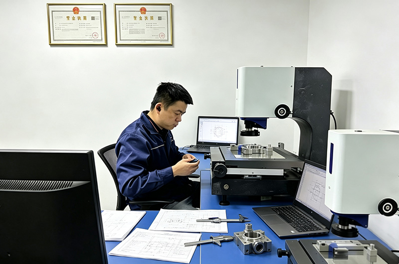
- The inspection method, if it is already fixed. CMM, height gauge, functional gauge, or a check fixture all imply different datum access.
- Any feature that has caused a problem before. If a bore has been the source of a dispute, we will machine and measure it first and tell you what we see.
If the scheme has a problem, we say so in the DFM note rather than in a rejection. Moving a datum on a drawing costs nothing. Discovering the problem at first article costs a week.
FAQ: datum selection
How many datums should a drawing have?
Three for a fully constrained prismatic part: a primary that stops three degrees of freedom, a secondary that stops two, and a tertiary that stops one. Fewer datums leave the part under-constrained and the measurement ambiguous. More than three are only justified when a specific feature needs its own reference for a functional reason, and that should be stated.
Can a hole be a primary datum?
Yes, when the part functions on that hole. A bore used as a primary datum stops two translations, and the face it is perpendicular to stops the rotation, so the pair works as a compound primary. The important thing is that the fixture can actually contact the bore over enough length, because a short bore gives a poorly defined axis.
What is the difference between a datum and a datum feature?
The datum is the theoretically exact plane, axis or point that tolerances are measured from. The datum feature is the real surface on the part, with its own imperfections, that the datum is derived from. Inspection derives the datum from the feature, which is why the quality of that feature matters as much as the tolerance attached to it.
Why do two labs get different results on the same part?
Usually because they built different datums: a different order, a different simulator, or a different number of contact points. Occasionally because one used a best-fit alignment, which distributes error across all measured points and hides the very deviation the drawing was written to control.
Does the datum need to be machined?
Not always, but if it is not machined the drawing has to say so and the tolerances referenced to it have to be sized for a raw surface. A cast or saw-cut face can move by several tenths of a millimeter, so a 0.02 mm relationship to it is not a requirement, it is a wish.
Send Us the Drawing
If you are not sure which face should be datum A, send the drawing and a photo of how the part sits in the assembly. We will tell you which scheme we would machine to, which one we would inspect to, and whether the two can be the same. If the answer is that the drawing needs one change, we will say that in a sentence rather than in a rejection report.
Free DFM on the drawing, a quotation within 24 hours, ±0.01 mm on the features we commit to, and more than 200 CNC machines in Dongguan behind the commitment. Send us the drawing, or reach us on WhatsApp at +86 17620300785 and by email at gongtianbao@xhlmarketing.com.